background image

D

EVICE

 P

ARAMETERS

Conference Composer User Guide

16

Technical Support: 800.932.2774

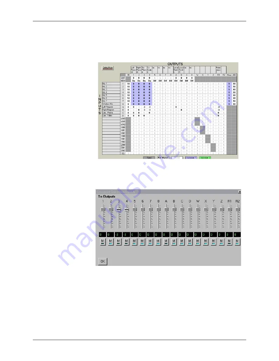
To change the gain of an entire row or column you may simply click on the column or 
row header (any of the labels 1-D on the columns or the rows) to see a collection of 
sliders as shown in Figure 13.  

The outputs R1 and R2 correspond to the echo canceller references R

EF

 1 and R

EF

 2.  

While these outputs are not physical outputs on the product, they allow you to build 
the echo canceller reference without using physical outputs from the device.  In the 
example in Figure 12, we used stereo program audio and consequently had a local left 
output (Output C) and a local right output (Output D) in the room.  The echo canceller 
reference R1 included both the codec audio (Input A), the phone add audio (Input B) 

Figure 12. 

The full cross point matrix for a system using a phone add, a codec, 

and stereo program audio.  Only the bold crosspoints are unmuted.

Figure 13. 

Cross point slider view of how Input A is used in all the output chan-

nels.

Summary of Contents for Conference Composer

Page 1: ...Conference Composer User Guide ...

Page 2: ...s are subject to change without notice The Polycom logo and Vortex are registered trademarks of Polycom Inc Polycom Inc Installed Voice Business Group 1720 Peachtree Street NW Suite 220 Atlanta GA 30309 2439 Phone 800 932 2774 404 892 3200 Fax 404 892 2512 www aspi com Technical Support 800 932 2774 vortex polycom com CCUG 0100 01 ...

Page 3: ...5 Device Parameters 8 System 8 Options 9 Mic Line Inputs 11 Input Filters 12 Automixer 13 EF Bus 14 Matrix Mixer 15 Output Filters 17 Outputs 17 Logic Input 18 Logic Output 19 Presets 20 Macros 20 Diagnostics 20 Project Files and Creating Reports 21 File Saving 21 File Restoring 21 Creating Reports 21 The Console Window 22 Console Tab 22 Properties Tab 23 Modem Use with the Vortex 25 Troubleshooti...

Page 4: ...M drive and run the Setup program If you have a previously installed version of Conference Composer on your computer it is highly recommended that you uninstall that version use Add Remove Program from the CONTROL PANEL window before installing the latest version After running the Setup program simply follow the instructions for installing Con ference Composer USING CONFERENCE COMPOSER WITH A VORT...

Page 5: ...ce and the meter indicates how full the command buffer is with commands being sent to the device 3 DSP LOAD Indicates the current percentage of used available variable DSP resources 4 MENUS FILE The File menu allows you to create a new Project Device Chain or Device manages file functions of a Project such as Opening Saving or Closing and handles printing and Preferences PROJECT The Project menu c...

Page 6: ...932 2774 USER MODE User mode selects between BASIC and ADVANCED Basic mode limits user options that can be adjusted Advanced mode allows con trol of all parameters available on Conference Composer HELP The Help menu contains the ABOUT option that shows the version number of the software ...

Page 7: ...t all the devices that are tied to a particular serial port on your computer controller The PROJECT rep resents a collection of DEVICE CHAINS You can think of the PROJECTS as directories the DEVICE CHAINS as files and the DEVICES as items in the files There are many different buttons and knobs that allow the user to change settings on the device Conference Composer s convention is that a feature a...

Page 8: ...ly to the device updating its configuration in real time Once Conference Composer has finished downloading the settings from the con nected devices you will see the Navigation area look like Figure 4 The amount of time it takes to sync with the Vortex depends on the number of presets that have valid data More presets means more data must be sent to the PC OFF LINE OPERATING WITHOUT AN EF DEVICE To...

Page 9: ...ENCE COMPOSER Polycom Inc 7 Conference Composer User Guide look like Figure 4 the red X s indicate that you are offline and you are ready to pro ceed to the next section Figure 5 Operating Conference Com poser Offline ...

Page 10: ...ts to outputs Holding the cursor over a particular block in the block diagram will show signal flow information from inputs to outputs or outputs to inputs depending on where you hold the mouse By holding the cursor over any output block you can see the all the inputs that map to the partic ular output You may enable disable specific features by left clicking on the blocks in the SYSTEM Page If a ...

Page 11: ... LED too easily The ability to follow signal flow and the Signal Activity LED can provide useful tools to ensure that the proper input to output mappings have been setup OPTIONS The OPTIONS tab allows the user to set the following parameters MODEM INITIALIZATION STRING The modem initialization string if enabled Figure 7 Signal Activity LED of Inputs and Outputs Figure 8 Options Tab ...

Page 12: ...he Vortex from the front panel LCD menu Users will be able to see what the settings in the device are but will not be able to change the device settings METER DISPLAY ON THE FRONT PANEL This parameter allows you to select which input output or reference is displayed on the front panel meter DEVICE NAME DEVICE ID when working off line The Vortex Device ID can be changed from the OPTIONS page only i...

Page 13: ...ut A to the remaining line level inputs The fields for Inputs 1 8 are as follows TEXT BOX This stores up to 16 character for the input label GATE LED This LED is active if the LEVELS button is enabled and the particular input gates on METER PER INPUT This shows the signal level if it is between 20dBu and 20dBu GAIN SLIDER AND TEXT BOX These allow the user to set the input gain in dB on the channel...

Page 14: ...mount of noise cancellation using NC LEVEL NC LEVEL ranges from 0 to 15 dB of cancellation The controls for the line level Inputs A D are simpler than the mic line inputs The user can select a Gain 0dB is the default and enable disable Mute The SIGNAL GENERATOR input allows the user to create a noise source either pink or white noise for use with noise masking applications or calibration of the Vo...

Page 15: ...sibly for camera positioning Please note that the automixers do not sum the gated inputs together the summing is performed in the matrix the automixer makes gating and level decisions and sends that information to the matrix The LOCAL MAX NOM can be set to limit the maximum number of open micro phones that can be open at a given time on the local Vortex In single Vortex applica tions this is the o...

Page 16: ...aximum number of open microphones Max NOM is set to be less than the number of microphones assigned to that automixer EF BUS The EF BUS page allows the user to configure how to combine the bus signals from the other linked Vortexes and control which echo canceller reference is sent to other devices as the Bus Reference Since there can be up to 8 Vortexes linked together and each device can put 4 d...

Page 17: ...ss points click and drag to select a rectangular area A slider control with a text box will appear to allow you to change the gain select mute unmute or on Inputs 1 8 choose the gated version of the Input If you are using signals for reinforcement and specifically want the gated signals at an attenuated level then set the gated crosspoint to the desired level such as 15 dB In general the gain of g...

Page 18: ... outputs on the product they allow you to build the echo canceller reference without using physical outputs from the device In the example in Figure 12 we used stereo program audio and consequently had a local left output Output C and a local right output Output D in the room The echo canceller reference R1 included both the codec audio Input A the phone add audio Input B Figure 12 The full cross ...

Page 19: ...equency response of the plots may be viewed by clicking on the GRAPH button The ENABLE button per filter enables disables that particular filter on the Output The ENABLE FILTERS button enables disables all filters on the particular Output Channel This button toggles with the Filter Bypass buttons per Output All filters for a partic ular output can be bypassed by clicking the BYPASS button Once the...

Page 20: ...lso have an LED associated with them to indicate the status of the contact closure A logic pin can have one of the following states unassigned assigned to a particular function macro or preset or assigned to one of four groups To assign a function to a pin single click and hold on the pin of the connector and select a colored assignment of the pin from the colored boxes that appear Figure 15 shows...

Page 21: ...trol win dows Right click in the ACTIVATED or DEACTIVATED field to pick a status off the menu list or type the command in directly As with the Logic Input pins the SHOW ACTUAL COMMAND button will show the command syntax To create status output that is a logical combination of particular inputs or outputs use the logical syntax 0 or 1 For instance to create a status output that will be set when Inp...

Page 22: ...at are executed sequentially when the macro is executed The user selects a macro to create and then sequentially puts the commands into the macro New commands may be inserted into the macro after the existing command by right clicking on an existing command and selecting either a command off the list or the INSERT COMMAND option which will let you type a command in directly You can also add new co...

Page 23: ...DEVICE or CANCEL Select UPLOAD SETTINGS TO DEVICE to upload the Project settings to the device You should set the Device IDs on the actual devices to match those in the project before uploading the Project Once uploading has started the display will present a status bar of the progress of uploading All Presets in the Project will be uploaded along with Project settings CREATING REPORTS Conference ...

Page 24: ...e capability to update firm ware To open a Console Window right click on the COM port in Conference Composer s Explorer menu and choose CONSOLE from the pull down menu that appears CONSOLE TAB WATCHING COMMANDS The larger window in the Console Tab displays communications between your PC and the EF Device Strings that are shown in blue text indicate a string sent by the PC Strings shown in red text...

Page 25: ...oFree firmware versions are listed below in Table 1 UPDATE YOUR EF DEVICE In Conference Composer software 1 Connect the RS 232 cable from your computer to the EchoFree device that you are updating Ensure that your serial port cable is wired with RTS and CTS for hardware flow control If you do not have RTS and CTS this process will not work and error messages will be displayed You can keep the devi...

Page 26: ...ue which indicates that your computer is communicat ing with the EF device Click on the UPDATE MICROCODE button 5 In the dialog box that comes up choose the EFB file for your appropriate device These EFB files are found in the directory where Conference Composer is installed Follow the instructions that come up in the dialog boxes NOTE When prompted by Conference Composer to perform a STANDARD UPD...

Page 27: ...S 232 cable from the Vortex and connect it to your modem You may need to use a null modem for your modem Connect your modem to the Vortex 4 Cycle power on the Vortex As it powers up it will send the initialization string to the modem Make sure the modem is On before cycling power on the Vortex If you don t have Conference Composer on site 1 Using a terminal program send the following strings to th...

Page 28: ...t your modem is connected to and make sure the box beside it is checked Click on the corresponding SETTINGS button In the dialog box that comes up go to the MODEM tab see Figure 21 below If the modems hang up before you connect increase the TIMEOUT time Choose the default string in the INITIALIZATION STRING pull down menu It should be the following string AT F1 E0 Q0 V0 K3 D0 Click on the box besi...

Page 29: ...indow open When the Vortex reboots you should see it send the modem initialization string to the terminal window If you are using the default modem init string you should see ATE0F1 B1S0 2 echoed in the terminal window If you don t see the string you will need to double check that the string is set cor rectly and that it is enabled MAKE SURE THE INITIALIZATION STRING IS SENT TO THE MODEM If you ar...

Reviews: