


26
27
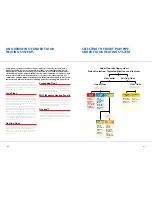
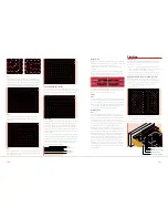
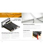
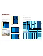
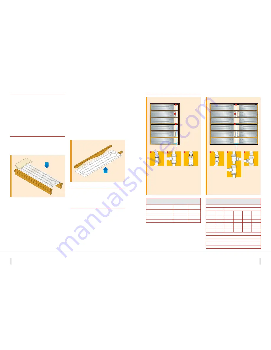
Panel layouts
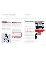
Pre-installation requirements
Planning
Before installing MHP panels ensure you have planned out the
positioning of the required panels avoiding all other services such
as electrics, gas and water supply.
You will not need to do any specific preparation for the
installation in a new build property as there will be no ceilings
or floors in place.
For existing room refurbishment, you will need to take up your
floor if fitting from above or take down the ceiling if fitting from
below. Ensure that the area where the MHP panels are to be
positioned is free from any debris before commencing installation.
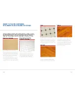
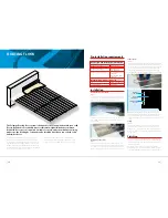
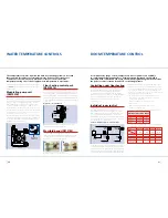
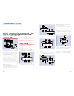
Installation
Installation from above
To install MHP panels from above simply fit support bearers to
each side of the joists. These support bearers should be positioned
30mm from the top of the joist and the MHP panel is then simply
laid on to these supports.
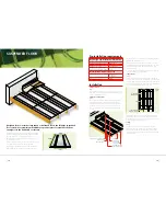
Installation from below
When installing MHP panels from below you will need to mark
out the positioning of the panels to ensure you have them
situated in the correct places for heating the room above.
Once you have checked the marked out positioning, the MHP
panels can be slotted into place and fixed to the underside
of the floor using 1¾” x 8 woodscrews with M6 x 30 dia washers.
It is advisable to use 6 fixings per panel ensuring you avoid the
moulded pipe marking on the underside of the panel and fix
each panel securely.
IMPORTANT NOTE:
Polystyrene can cause deterioration to cable
insulation when it comes into direct contact with it.
Always ensure that electrical cables are not in physical contact
with the MHP panels using tape or a polythene strip.
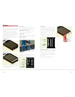
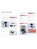
Finishing
Once you have connected your system up to the manifold and
tested it you can then finish the room by fitting the floor or ceiling
in the normal way depending on whether you have installed MHP
from above or below.
Testing
Where possible installations should be tested at 20°C to
18 bar pressure. Any installations once connected to the manifold
have a maximum test pressure of 6 bar.
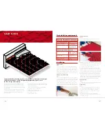
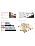
Product Information
Product
Code
No of panels
per pack
MHP 490mm (W) x 2.0m (L)
MHP49020
5
MHP 490mm (W) x 1.3m (L)
MHP49013
5
MHP 380mm (W) x 2.0m (L)
MHP38020
5
MHP 380mm (W) x 1.3m (L)
MHP38013
5
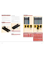
Heat Output
Maximum floor area for flow and return 20m
2
Room at 20°C
Heat output per panel
Flow
Av. floor
MHP49020 MHP49013 MHP38020 MHGP38013
temp (°C)
temp (°C)
(W)
(W)
(W)
(W)
40
25.0
63
42
49
33
45
25.8
75
50
58
39
50
26.6
86
58
67
45
55
28.9
120
80
93
62
60
30.8
147
99
114
77
Approximate coverage required:
For 70W/m
2
room
= 80% coverage
For 50W/m
2
room
= 60% coverage
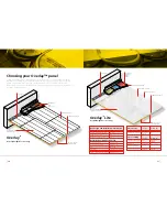
Connect up to 3 panels in series
Maximum coverage per circuit 20m
2
1 panel layout
15mm Polypipe flow and return
connections to manifold
15mm Polypipe flow and return
connections to manifold
Part No: PB010
10mm
Straight Coupling
Part No: PB010
10mm
Straight Coupling
Part No: PB1115
15mm - 10mm
Reduced Branch Tee
Part No: PB015
15mm
Straight Coupling
+
Part No: PB1815
15mm - 10mm
Socket Reducer
Part No: PB1115
15mm - 10mm
Reduced Branch Tee
+
Part No: PB1815
15mm - 10mm
Socket Reducer
Part No: PB1115
15mm - 10mm
Reduced Branch Tee
+
Part No: PB1215
15mm - 10mm
Reduced Branch
Spigot Tee
2 panel layout
1
1
2
3
2
3
4
4
5
5
6
6


