38
39
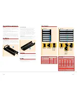
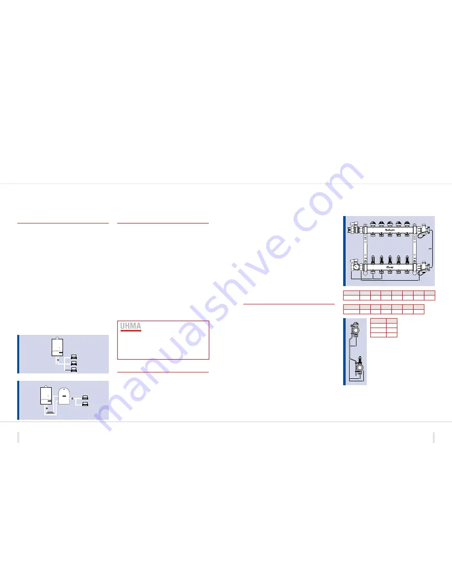
MANIFOLDS
Manifolds are common to all systems above 30m
2
, independent of the under floor heating
system. Manifolds are supplied complete and fixed to the wall mounting bracket.
The manifold comes complete with a drain and air vent assembly,
which can be positioned on either end of the manifold. Isolation
valves are supplied separately for the supply end of each manifold.
The bottom manifold is the flow and the top manifold is the
return. Each manifold port comes complete with a Polyplumb
push fit connection. Pipes are connected to manifolds by
inserting a pipe stiffener into the pipe and simply push fitting
the pipe into the port.
The flow meter on each flow port of the manifold provides
a visual indication of the flow through each circuit.
Both manual and lockshield balancing can be undertaken
by either using the blue cap on the return manifold for manual
adjustment, or removing the blue cap and adjusting using the
key supplied with each manifold.
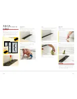
Preparing and installing
the manifold
Remove the manifold from the box and arrange the flow and
return manifolds to ensure that the inlets/outlets are pointing
downwards. Remove the air vent and drain valve from the
packaging and connect to the desired end of the manifold.
Ensure the seal is correctly in place before tightening the
compression nut by hand on to the manifold. To ensure
the valves are securely connected to the manifold, use a
38mm spanner or wrench to tighten by a further half turn.
Remove the isolating valves (supplied separately) from the packaging
and connect to the opposite end of the manifold. As with
the air vent and drain valve, ensure the seal is correctly in
place before tightening the compression nut by hand on to
the manifold. Then, complete the connection by using a 38mm
spanner or wrench to tighten by a further half turn.
Fix the manifold horizontally in the desired position utilising
both screw holes on each bracket.
The manifold is now in position and ready to be connected
to the mains from the boiler and the under floor heating pipe
circuits. A set of self adhesive stickers are included to help
identify each circuit on the manifold. The stickers also provide
the opportunity to record the number of turns required for the
correct flow rate through each circuit (for further information
on testing and commissioning see pages 46 and 47).
62
L
80
50
A
B
C
Outlets
2
3
4
5
6
7
8
L (mm)
190
245
300
355
410
465
520
Outlets
9
10
11
12
13
14
L (mm)
575
630
685
740
795
850
Dimension
1”
A (mm)
39
B (mm)
64
C (mm)
86
CONNECTING TO HEAT SOURCE
Polypipe under floor heating systems are designed to be connected to a variety
of heat source options.
Gas and oil boilers
When connecting to any heat source it is essential that the under
floor heating manifold(s) are fed directly from the heat source with
a dedicated set of flow and return primaries, to enable total
independent hydraulic control of the under floor heating system.
Under no circumstances should this primary feed be connected
into any other heating pipework, such as radiator or domestic
hot water primary circuits.
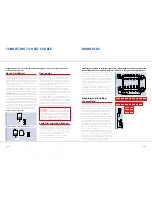
To provide independent hydraulic control of the entire system, it is
important that the installation is designed as an ‘S Plan’ or ‘S Plan Plus’
configuration which allows for a two port zone valve to be fitted to all
primary circuits and at each under floor heating manifold (see diagram).
IMPORTANT NOTE:
Under no circumstances should a Polypipe
under floor heating system be connected in to a ‘Y Plan’ (flow share)
system as this will result in serious system operating problems.
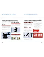
To ensure that the correct operating temperatures and system flow
rates are maintained for the under floor heating system, the manifold(s)
should be fitted with a manual blending valve and circulating pump
(see section ‘Water temperature controls’). However, it is the
responsibility of the designer/installer to ensure that the boiler and
system pump are capable of providing sufficient outputs in order
to meet the requirements of the primary pipework, the under floor
heating system and any other equipment installed in the system.
Typical ‘S Plan Plus’ configuration
Typical ‘S Plan Plus’ configuration via thermal store
Heat pumps
Polypipe under floor heating systems are ideal for use with heat
pump systems due to the lower operating temperatures that
are produced by this type of heat source. However, to provide
temperature limitation protection and sufficient system flow
rate for the under floor heating installation, it is recommended
to fit the manual blending valve and pump pack as supplied
by Polypipe Building Products Ltd.
It is the responsibility of the system design/installer to ensure that
the heating circulation pump supplied with the heat pump,
and any associated primary pipework, is capable of providing
sufficient duty to meet the demand up to the under floor heating
manifold assembly. This also applies if a ‘buffer tank’ has been
fitted to the heat pump installation.
A buffer tank or thermal store is often fitted between the heat
pump and the under floor heating system. This is to provide
a sufficient quantity of stored water to feed the under floor heating
system and to ensure that the heat pump flow rates are maintained,
thereby reducing the risk of cycling. By using a buffer tank
installation there is no need to use ‘open circuits’ at the under
floor heating manifold, therefore allowing individual room control.
The Underfloor Heating Manufacturers
Association (UHMA) do not recommended
that the under floor heating system be used
as an ‘open circuit’, to provide the flow rate requirement for
the heat pump installation, as this could lead to problems
with system control at a later date. For further information
regarding the installation of the system please contact the
Polypipe Technical Hotline on
01709 770000
.
Solid fuel and wood burners
Under no circumstances should a Polypipe under floor heating
system be connected directly to this type of heat source.
Instead, the burner should be used to provide indirect heat via
a thermal store or similar neutraliser. The low temperature feed
from this store can then be pumped to the under floor heating
manifold, as with a heat pump installation.
Please seek specialist advice from the heat source supplier
or manufacturer before commencing the installation.

