background image


10 


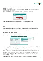
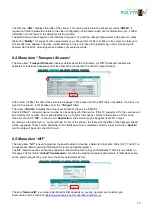
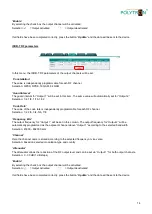
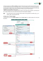
The first line, 

URL

,

 displays the URL of the stream. This can be copied into the stream list under 

URL/IP

, i

required. All other parameters relate to the video configuration of the camera and are for information only.  Further 
information can be found in the data sheet of the camera.  
The listed data can be changed in the interface if required. To send the changed parameters to the camera, press 
the button 

Modify

“.  Changes of some parameters (e.g. change from H.264 to H.265 or vice versa) can take up to 

10 seconds to be applied. The video control window is only a reference for programming, not for monitoring the 
camera! Note that the video signal has a latency of several seconds. 


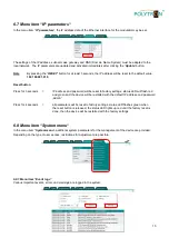
6.4 Menu item 

“Transport Streams“


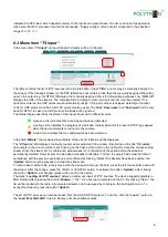
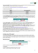
The menu item 

Transport Streams

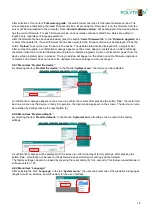
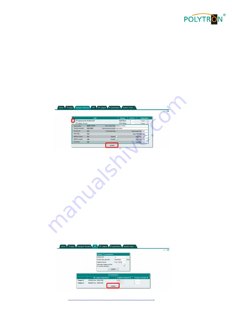
“, displays details about the IP streams. All MPTS transport streams are 

extracted to individual independent services that can be forwarded to each RF output channel.  


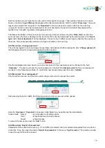
In the column 

Title

,


the title of the service is displayed. This is taken from the SDT table, if available. If a title is not 

found in the stream, it will be taken from the 

TS input


table

The column 

Bitrate

“ indicates the actual input bit rate of the service in Mbit/s. 

Under 

LCN v.1

“, a logical channel number can be assigned for the service. If the TV supports LCN, the services will 

be sorted by this number. Zero means that there is no LCN for this channel. Further information on LCN can be 
found in section 6.5 

NIT

“. In the column “

Destination

,


the service may be assigned to the RF output.  

By clicking on the plus sign 

+“

 on the left side in front of the stream, the table with the PIDs of the transport stream 

will be expanded. These can be edited here. If all fields have been completed correctly, press the button 

Update


and the data will be sent to the HDI 2 multi.  


6.5 Menu item 

“NIT“ 

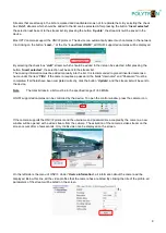
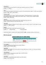
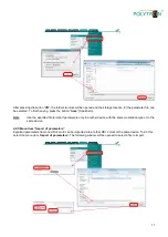
The menu item 

NIT

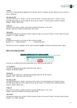
“ is used to program the specific data for creating a Network Information Table (NIT). The NIT is 

a transponder table containing information for receiving digital programs.   
The NIT creation requires advanced expertise in transmission technology and standards! There are two tables on 
this page. The first table 

Global TS parameters

,

 contains the high-level network parameters. If other devices are 

on the same network, they must have the same parameters as this. 


The item 

Network ID

“ is a network identification that depends on country, operator and network type.  

Exact values can be found at 

https://www.dvbservices.com/identifiers/network_id


Summary of Contents for HDI 2 multi

Page 1: ...1 HDI 2 multi IP Modulator IP into DVB C DVB T ISDB T Manual 0902252 V1...

Page 2: ..._________________________________________16 6 8 2 Menu item Change password ___________________________________________16 6 8 3 Menu item User management ___________________________________________17...

Page 3: ...dripping and splashing water If there is condensation wait until the device is completely dry Operating environment according to the specified IP protection class Caution Danger of life According to t...

Page 4: ...efined packing and transportation materials Damage caused by faulty connections and or improper handling are excluded from any liability Waste disposal Electronic equipment does not belong in househol...

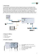
Page 5: ...easy programming The management and the connection of the IP transport stream takes place via an RJ45 100Mbit s interface The IP modulator offers the possibility to feed IP camera signals into the cab...

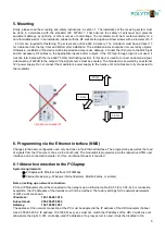
Page 6: ...connect the modulator s power supply to the mains until all cables are fully connected to the modulator 6 Programming via the Ethernet interface NMS Changes to the basic configuration can only be done...

Page 7: ...device homepage will display the main information about the device and its status File tabs for programming the HDI 2 multi are available at the top of the window In the device description Device info...

Page 8: ...ndicates that no valid stream has been detected In the field Bitrate the measured input bitrate of the stream in Mbit s will be displayed The CC errors field displays continuity counter errors detecte...

Page 9: ...to give all inserted cameras a name under the item Title If the camera requires a password the fields Username and Password must be completed If all fields have been completed correctly click the but...

Page 10: ...ates the actual input bit rate of the service in Mbit s Under LCN v 1 a logical channel number can be assigned for the service If the TV supports LCN the services will be sorted by this number Zero me...

Page 11: ...activated If a different value is desired clear this check box and enter the value manually Normally the Original network ID is the same for all output channels throughout the network Exact values ca...

Page 12: ...the reduction of the RF output level and can be set via Output 1 for both output channels Selection 0 30 dB 1 dB steps Enable By selecting the check box the output channel will be activated Selection...

Page 13: ...vated If all fields have been completed correctly press the button Update and the data will be sent to the device DVB C Annex B RF parameters In this menu the DVB C Annex B RF parameters of the output...

Page 14: ...ly programmable for each RF channel Selection 1 2 2 3 3 4 5 6 7 8 Frequency kHz The output frequency for Output 1 will be set in this column The output frequency for Output 2 will be automatically pro...

Page 15: ...password will be reset to factory settings status LED will flash red and green and the device will be restarted with the default IP address and password admin Press for 4 seconds all parameters will b...

Page 16: ...can change his username and password After pressing the item Change password the following window for changing the password will be opened Only the dedicated username admin cannot be changed All other...

Page 17: ...n Note Use the exported file to import parameters only to another device with the same modulation type or to the same device 6 8 5 Menu item Import of parameters Exported parameters from one HDI 2 mul...

Page 18: ...which the file was exported Press the button Upload to send the parameters to the device The import of parameters from one software release to another is also allowed New parameters or parameters tha...

Page 19: ...s in process The login window will appear on the screen once the firmware upgrade is complete The browser does not need to be updated All device settings remain unchanged 6 8 7 Menu item Restart the d...

Page 20: ...ill be accepted 6 8 11 Menu item Date time In the menu item Date time in the tab System menu the user can specify the time source for the IP modulator Local time shows the time taking into account pos...

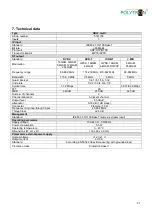
Page 21: ...2 2 3 3 4 5 6 7 8 Symbol rate 1 7 2 MSps 5 057 6 36 MSps FFT 2K MER 40 dB 35 dB 40 dB Number of channels 2 Channel allocation Adjacent channel Output level 90 dB V Attenuator 0 30 dB 1 dB steps Connec...

Page 22: ...22 Notes...

Page 23: ...23 Notes...

Page 24: ...hme H Q Order department 49 0 70 81 1702 0 Technische Hotline Technical hotline 49 0 70 81 1702 0 Telefax 49 0 70 81 1702 50 Internet http www polytron de Email info polytron de Technische nderungen v...

Reviews: