28
3. Function and control elements
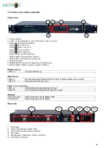
Front view
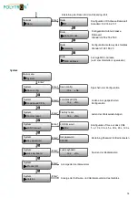
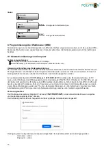
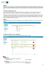
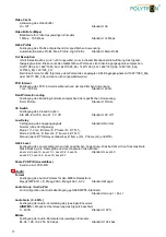
1 Power indicator
2 Lock 1, Lock 2 SDI status, Lock 3 ASI status, Lock 4 not used
3 Buttons for manually programing
Button up in the menu
Button down in the menu
Button left in the menu
Button right in the menu
Button
„Enter“(confirm selection)
Button
„Back“ (one step back in menu)
Button
„Menu“ (enter menu and leave it)
4 Streaming output
5 Management connector for programing via web browser
6 Alarm indicator, lights up, when no signal is present
Power
(green)
LED on
Device switched on
Alarm
(red)
LED on
No standard signal detected at the input or data overflow at the output
LED off
Signal detected at the input
Lock 1, 2, 3, 4
(green)
LED on
Standardized signal detected at input
LED off
No standardized signal detected at the input
IP ports
IP stream port
RJ45, Ethernet 10/100 Mbit/s, UDP
IP data port
RJ45, Ethernet 10/100 Mbit/s
Rear view
7 SDI inputs
8 ASI in (ASI transport stream input)
9 ASI out (ASI transport stream outputs)
10 RF output
11 Mains switch / mains fuse / mains connection
12 Grounding connection
1
2
3
4
5
6
11
9
8
7
10
12

