background image


47 
 

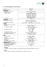
10. Technische Daten / Technical data 


Typ / Type 

HDS 2 C/IP


Artikel-Nr. / Article no. 

5741697


Encoder Video 
 

Videoformat / Video Format 


Eingang / Input 


Auflösung / Resolution 


Low Delay 


Aspekt-Ratio / Aspect ratio 


MPEG2, MPEG4 AVC/H.264


2x SDI


1920*1080_60p, 1920*1080_50p, 

(-for MPEG4 AVC/H.264 only) 

1920*1080_60i, 1920*1080_50i, 
1440*1080_60i, 1440*1080_50i, 

1280*720_60p, 1280*720_50p 

720*480_60i, 720*576_50i


Normal, Mode 1, Mode 2


16:9, 4:3


Encoder Audio 
 

Audioformat / Audio Format 


Samplingrate / Sampling Rate 


Bit Rate 


MPEG1 Layer II;MPEG 2-AAC; 

MPEG 4-AAC, Dolby Digital AC3 2.0 

48 kHz 

64 kbps, 96 kbps, 128 kbps, 192 kbps, 256 kbps, 320 kbps


Modulator 
 

Ausgangskanäle / Output Channels 


Standard  


Konstellation / Constellation 


Bandbreite / Bandwidth 


Symbolrate / Symbol Rate 


Ausgangsfrequenz / Output Frequency 


Ausgangspegel / Output Level 


4


J.83A (DVB-C), J.83B, J.83C 

wählbar / selectable 

J. 83A   16 / 32 / 64 / 128 / 256 QAM 

J. 83B   64 / 256 QAM 
J.83C   64 / 256 QAM 

J.83 A   8 MHz 
J.83B  

6 MHz 

J.83C 

6 MHz 

3…9 MSps 

50…960 MHz (1 kHz-Schritte / steps) 

-

20…3 dBm (89…112 dBµV) 

(0,1 dB-Schritte / steps)


System 
 

Ausgänge / Outputs 


Bitrate ASI  


Fernsteuerung / Remote Control  


NMS Interface 


Stream Port 


IP-Verschlüsselung / IP Encoding 


IP-Protokoll / IP Protocol 


1x HF (F) / 1x RF (F), 

2x ASI (BNC), IP (RJ45) 

80 Mbps 

Web-Interface per Ethernet IP 

RJ45, 100 Mbps 

RJ45, 1000 Mbps (4 MPTS, 2 SPTS) 

ETSI TS 102034 

IPv4 Multicast (SMPT)


Betriebsparameter / Operating Parameters
 

Stromversorgung / Power Supply 


Betriebstemperatur / Operating Temp. 


Abmessungen / Dimensions 


Gewicht / Weight 


100…240 V

AC 

(50/60 Hz) 

0…45 °C 

482 x 242 x 44 mm 

3,7 kg


(1) 

HINWEIS


Die meisten TV-Geräte unterstützen den Standard 1080P über den Antenneneingang (Tuner) nicht! 


(1) 

NOTE


Most TV sets do not support the standard 1080P via the antenna input (tuner)! 


Summary of Contents for HDS 2 C/IP

Page 1: ...2x SDI ASI in DVB C ASI IP SDI Encoder Modulator HDS 2 C IP Bedienungsanleitung User manual 0902547 V1...

Page 2: ...atus indication Welcome 16 38 8 3 Men s Encoder 1 und Encoder 2 Menus Encoder 1 and Encoder 2 16 38 8 4 Men Modulator DVB C Menu Modulator DVB C 18 40 8 5 Men TS Config Menu TS Config 19 41 8 6 Men Ou...

Page 3: ...stolperfrei mit einer Schlaufe verlegt werden damit das Kondenswasser und oder bei Schwitz wasserbildung kein Wasser ins Ger t l uft sondern auf den Boden tropft Aufstellungsort w hlen Planen sie den...

Page 4: ...es Material flie en kann Um die Zuverl ssigkeit von ESD Baugruppen gew hrleisten zu k nnen ist es notwendig beim Umgang damit die wichtigsten Handhabungsregeln zu beachten Nur an elektrostatisch gesch...

Page 5: ...e und an 2 ASI Transportstrom Ausg ngen zur Weiterverarbeitung zur Verf gung Die Ger te unterst tzen die Encodierung von MPEG2 HD SD und MPEG4 AVC H 264 HD SD Signalen welche als SDI Signale und ASI T...

Page 6: ...rogrammierung via Web Browser 6 Alarm Anzeige wenn kein Signal anliegt Power gr n LED an Ger t eingeschaltet Alarm rot LED an Kein normgerechtes Signal am Eingang erkannt oder Daten berlauf am Ausgang...

Page 7: ...7 4 Blockschaltbild SDI 1 MPEG 2 MPEG 4 HD Encoding MPEG 2 MPEG 4 HD Encoding M U X ASI IN DVB C Modulator 1 4 RF OUT SDI 2 ASI 1 2 OUT IP OUT TS Auswahl SPTS1 SPTS2 MPTS1 4...

Page 8: ...G2 Auto Normal 14 Main Profile Level 4 0 Mpeg 2 192 kbps 100 IP ASI Output IP DATA Port Service IP Subnetzmaske Gateway ASI MPTS 1 aktiviert 192 168 002 136 255 255 255 000 192 168 002 000 MPTS 1 Modu...

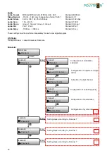
Page 9: ...b des Men s Start up Please wait Encoder Modulator 192 168 1 225 Anzeige Alarmmeldungen und der Laufzeit des Ger tes Einstellungen der Modulatoren Channel 1 Channel 2 Channel 3 Channel 4 Konfiguration...

Page 10: ...264 Level Level 2 2 Level 3 Level 3 1 Level 3 2 Level 4 Standard Level 4 Level 4 1 Level 4 2 Level 5 Level 5 1 OUT Resolution Auto 1920 1080_60i 1920 1080_50i Standard Auto 1440 1080_60i 1440 1080_50i...

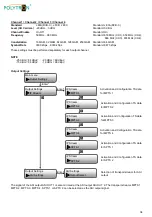
Page 11: ...urchgef hrt werden ASI Status Transportstrom Locked Unlocked Datenrate Modulator Enter Main menu Modulator Modulator Channel 1 Channel 1 Standard Channel 1 Frequency Channel 1 Constellation Channel 1...

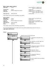
Page 12: ...es ASI Ausganges ASI OUT 1 liegt gespiegelt auch am ASI Ausgang ASI OUT 2 an Als ASI Signal k n nen die Transportstr me MPTS 1 MPTS 2 MPTS 3 MPTS 4 SPTS 1 oder SPTS 2 ausgew hlt werden Enter Enter IP...

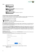
Page 13: ...2 3002 Output protocol UDP RTP RTSP Standard UDP Bitrate einstellbar Standard 20 0 Mbps Diese Einstellungen m ssen f r jeden SPTS separat durchgef hrt werden Nach erfolgreicher Programmierung kann de...

Page 14: ...seinstellungen Load saved CFG Main menu System System Save config Save config Yes No System Factory reset System Load saved CFG Enter Yes No Factory reset Enter Yes No Enter Konfiguration Time out des...

Page 15: ...tzwerkanschlusses im PC muss an die IP Adresse des HDS angepasst werden Subnetmask 255 255 255 0 IP Adresse 192 168 001 xxx xxx darf dabei nicht exakt mit der IP Adresse des HDS Ger tes bereinstimmen...

Page 16: ...n punkte in der linken Spalte alle notwendigen Parameter Einstellungen vorgenommen und auf dem Ger t gespeichert werden Durch Anwahl des entsprechenden Registerbuttons gelangt man in die zuge h rigen...

Page 17: ...schen Anwendung Field Picture Standard Picture CC Switch Festlegung des Closed Caption EIA 608 EIA 708 Line 21 CC Off Standard CC Off Low Delay Verz gerung des Ausgangssignals Standard Normal Normal o...

Page 18: ...werden In diesem Men werden die Parameter f r alle In diesem Men werden die Parameter je HF Ausgangs HF Ausgangskan le eingestellt Gem der kanal eingestellt Die bernahme der Einstellungen angegebenen...

Page 19: ...dulator wird der Ausgangspegel f r alle aktivierten Kan le angezeigt Im Einstellmen f r den jeweiligen Kanal wird der Ausgangspegel des angew hlten Modulator Ausgangs konfiguriert Der Gesamtpegel am A...

Page 20: ...fernen Anwahl aller Eingangsprogramme Anwahl aller Ausgangsprogramme Programmanalyse am Eingang Zeitbegrenzung der eingangsseitigen Programmanalyse Die Vergabe der programmspezifischen Daten erfolgt d...

Page 21: ...Port und der erfolgt durch Bet tigen des Buttons Apply Schrittweite Step werden die nachfolgenden Ports automatisch vergeben Die bernahme der Einstellungen erfolgt durch Bet tigen des Buttons Apply Im...

Page 22: ...en Ebenso erfolgt hier die Konfiguration des Datenports DATA f r den Ausgang der IP Signale 9 2 Men Password Das Men Password erm glicht die nderung der Zugangsdaten zum Ger t und dadurch eine Erh hun...

Page 23: ...rd eine Sicherungsdatei auf dem PC Laptop gespeichert Load Durch Bet tigen des Buttons Durchsuchen die Backupdatei im PC Laptop ausw hlen und durch Anklicken des But tons Load config das Laden der aus...

Page 24: ...werden Daf r m ssen die IP Einstellungen korrekt sein und es muss sichergestellt werden dass das Ger t auf den NTP Server zugreifen kann um die korrekte Uhrzeit zu erhalten 9 6 Men Log Im Men Log werd...

Page 25: ...fields in the surroundings Too strong a heat effect or accumulation of heat will have an adverse effect on the durability Don t mount directly over or near heating systems open fire sources or the li...

Page 26: ...defined packing and transportation materials Damage caused by faulty connections and or improper handling are excluded from any liability Recycling All of our packaging materials packaging identificat...

Page 27: ...and as well as at 2 ASI transport stream outputs for further processing The devices supports the encoding of MPEG2 HD SD and MPEG4 AVC H 264 HD SD signals which can be supplied as SDI signals and ASI...

Page 28: ...rm indicator lights up when no signal is present Power green LED on Device switched on Alarm red LED on No standard signal detected at the input or data overflow at the output LED off Signal detected...

Page 29: ...29 4 Block diagram SDI 1 MPEG 2 MPEG 4 HD Encoding MPEG 2 MPEG 4 HD Encoding M U X ASI IN DVB C Modulator 1 4 RF OUT SDI 2 ASI 1 2 OUT IP OUT TS selection SPTS1 SPTS2 MPTS1 4...

Page 30: ...PEG2 Auto Normal 14 Main Profile Level 4 0 Mpeg 2 192 kbps 100 IP ASI Output IP DATA Port Service IP Subnet mask Gateway ASI MPTS 1 activated 192 168 002 137 255 255 255 000 192 168 002 000 MPTS 1 Mod...

Page 31: ...Encoder Modulator 192 168 1 225 Display of alarm messages and the running time of the device Adjustments of the modulators Channel 1 Channel 2 Channel 3 Channel 4 Configuration of the NMS and data po...

Page 32: ...3 Level 3 1 Level 3 2 Level 4 Standard Level 4 Level 4 1 Level 4 2 Level 5 Level 5 1 OUT Resolution Auto 1920 1080_60i 1920 1080_50i Standard Auto 1440 1080_60i 1440 1080_50i 1280 720_60p 1280 720_50...

Page 33: ...atus Transport stream Locked Unlocked Data rate Modulator Enter Main menu Modulator Modulator Channel 1 Channel 1 Standard Channel 1 Frequency Channel 1 Constellation Channel 1 Symbol Rate Configurati...

Page 34: ...the ASI output ASI OUT 1 is also mirrored at the ASI output ASI OUT 2 The transport streams MPTS 1 MPTS 2 MPTS 3 MPTS 4 SPTS 1 or SPTS 2 can be selected as the ASI output signal Enter Enter IP Stream...

Page 35: ...TS 1 3001 SPTS 2 3002 Output protocol UDP RTP RTSP Standard UDP Bitrate adjustable Standard 20 0 Mbps These settings must be performed separately for each SPTS After successful programming the IP Stre...

Page 36: ...tory settings Load saved CFG Main menu System System Save config Save config Yes No System Factory reset System Load saved CFG Enter Yes No Factory reset Enter Yes No Enter Configuration of time out o...

Page 37: ...of the network connection in the PC must be adapted to the IP address of the HDS subnet mask 255 255 255 0 IP address 192 168 001 xxx xxx must not exactly match the IP address of the HDS device The d...

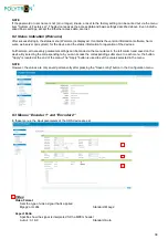
Page 38: ...rthermore all necessary parameter settings can be made via the menu items in the left column and saved on the device By selecting the corresponding tab you can access the corresponding submenus In eac...

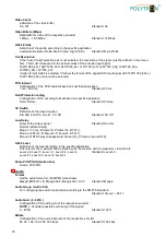
Page 39: ...pplication Field Picture Standard Picture CC Switch Definition of the closed caption EIA 608 EIA 708 Line 21 CC Off Standard CC Off Low Delay Delay of the output signal Standard Normal Normal without...

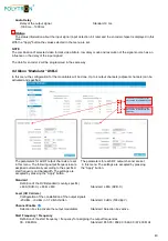
Page 40: ...or each RF output channel are set in this menu The following output frequencies are in this menu The settings are accepted by pressing assigned automatically according to the specified the Apply butto...

Page 41: ...el at the output is reduced by 3 dB each time the activated output channels are doubled compared to the individual output level Example Single output level Channel 1 Channel 4 6 dBm Total output level...

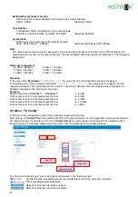
Page 42: ...The program specific data will be assigned by clicking on the respective program at the TS output The values selected in the menu are set with the Apply button The General button is used to adapt the...

Page 43: ...menu Press the button Apply and the data will automatically to the specified IP address the port be sent to the device and the increment Step Press the button Apply and the data will be sent to the de...

Page 44: ...data port DATA for the output of the IP signals are also configured in this menu 9 2 Menu Password In the Password menu the currently logged in user can change the access data username password to th...

Page 45: ...n Backup config a backup file is stored on the PC laptop Load Select the backup file in the PC laptop by clicking on the Browse button and activate the loading of the selected con figuration file onto...

Page 46: ...e server must be specified For this the IP settings must be correct and the device must be able to access the server to get the correct time 9 6 Menu Log In the Log menu the Log data will be displayed...

Page 47: ...z Output Frequency Ausgangspegel Output Level 4 J 83A DVB C J 83B J 83C w hlbar selectable J 83A 16 32 64 128 256 QAM J 83B 64 256 QAM J 83C 64 256 QAM J 83 A 8 MHz J 83B 6 MHz J 83C 6 MHz 3 9 MSps 50...

Page 48: ...hme H Q Order department 49 0 70 81 1702 0 Technische Hotline Technical hotline 49 0 70 81 1702 0 Telefax 49 0 70 81 1702 50 Internet http www polytron de eMail info polytron de Technische nderungen v...

Reviews: