11
WARNING:
The SD card is provided to the device. Removing it will cause the
operation data lost.
(3) PCS Module
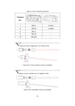
Figure 4.3.3: PCS Front View
Table 4.3.3: PCS Parts
Parts
Functions
AC Input /
Output
GRID: Grid input
GEN: Generator input
LOAD: Load output
GND: Power ground
Power Supply
Status
Indicate the power supply status:
On: Normal
Off: No power
MAIN
Load output switch
BAT
Battery bus, connect to Solar Controller
Generator Start
and Stop
START-A&START-B: Start generator
STOP-A&STOP-B: Stop generator
Synchronizing
Signal
Reserved
DC 12V
DC12V power supply output
EMS
Communicate with EMS module
EMS
CAN
MAIN
GND
SYN
START-A
START-B
STOP-A
STOP-B
DC 12V
GRID
GEN
LOAD
DC 12V
DC 12V
1
2
3
4
ON
DIP
ADD
STATUS
BAT
AC Input / Output
Power Supply Status


