background image


1. Preface 

Thank  you  for  purchasing  POMCube  iCAN  NetZero,  an  intelligent  energy 

system that helps provide a fully integrated power system for you. In order to 

use  your  device  safely,  efficiently  and  effectively,  please  read  the  User 

Manual  thoroughly  and  follow  the  instructions  provided  before  use.  Please 

keep this User Manual for future reference.   

POMCube  reserves  the  right  to  change  products  information  and 

specifications without notice. 

Products and specifications discussed herein 

are for reference purposes only. All information discussed herein may change 

without  notice  and  without  warranties  of  any  kind.  This  document  and  all 

information  discussed  herein  remain  the  sole  and  exclusive  property  of 

POMCube.   

NetZero  system  may  be  updated  for  technical  reasons  without  prior  notice. 

Purchasing  this  product  indicates  that  you  have  acknowledged  it  and 

accepted it. 

Copyright© 2019 POMCube Inc. All rights reserved. 


Summary of Contents for iCAN NetZero

Page 1: ...iCAN NetZero User Manual Intelligent Energy System ICN1V1 0 4 ...

Page 2: ......

Page 3: ...atures 5 4 3 Specification 6 4 4 Parts and Functions 7 5 Installation 16 5 1 Tools and Safety Gear 16 5 2 Assemble the Rack 16 5 3 Install the Modules 18 5 4 Internal Wiring 19 5 5 External Wiring 21 6 Basic Operations 24 6 1 Boot System 24 6 2 Shut Down System 24 6 3 Getting Started with NetZero App 25 6 4 Network Connection 25 6 5 Reset Network 26 7 Troubleshooting 26 8 Emergency Situations 28 9...

Page 4: ...reserves the right to change products information and specifications without notice Products and specifications discussed herein are for reference purposes only All information discussed herein may change without notice and without warranties of any kind This document and all information discussed herein remain the sole and exclusive property of POMCube NetZero system may be updated for technical ...

Page 5: ...cycling please contact your local city office your household waste disposal service or the shop where you purchased the product 2 2 FCC Statement This device complies with Part 15 of the FCC Rules Operation is subject to the following two conditions 1 This device may not cause harmful interference and 2 This device must accept any interference received including interference that may cause undesir...

Page 6: ...circuit different from that to which the receiver is connected Consult the dealer or an experienced radio TV technician for help RF Warning Statement The device has been evaluated to meet general RF exposure requirement The device can be used in portable exposure condition without restriction 3 Safety Instructions WARNING These safety instructions provide important safety information and should be...

Page 7: ...nough to take the full weight of it 3 Keep the device away from direct sunlight or moisture 4 Keep the device away from heat sources such as stovetops or ovens 5 Do not subject the device to extreme temperatures 6 Do not subject the device to strong impact or vibration 7 Keep the device away from potentially dangerous location such as flammable explosive chemical laden or wet atmospheres where pet...

Page 8: ... the source of energy repeatedly NetZero automatically selects the most economical reliable and sustainable energy while keeping the system running 24 7 without human intervention The ultimate goal for NetZero is to eliminate the reliance of conventional power produced from fossil energy and maximize the use of clean energy whether they are locally generated or from the grid 4 2 Features 1 Automat...

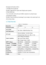
Page 9: ...odel No PNZ BBS1 Battery Quantity 4 5 6 AC1 Grid 90 140Vac 50 60 5Hz Max 63A AC2 Generator AC Load 5 0kVA 50 60Hz 110 120 127Vac Overload Cap 120 3s 150 0 15s Solar Controller Input Voltage 200 650Vdc Max Input Power 6 6kW Max Charge Power 5 0kW MPPT Voltage 245 550Vdc 300 550Vdc 360 550Vdc Capacity 100 1 44 8V90Ah 16 1kWh 20 2kWh 24 2kWh 51 2V90Ah 18 4kWh 23 0kWh 27 6kWh Dimension H W D 1750 570 ...

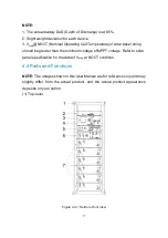
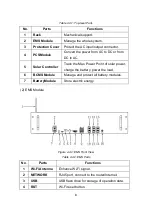
Page 10: ... should be greater than the minimum voltage of MPPT voltage Refer to solar panel specification for the data of Vmpp at NOCT condition 4 4 Parts and Functions NOTE The images shown in this User Manual are for reference only and may slightly differ from the actual product and the actual product appearance depends on your option 1 Top level Figure 4 4 1 NetZero Front View ...

Page 11: ...5 Solar Controller Track the Max Power Point of solar power charge the battery power the load 6 BCMS Module Manage and protect all battery modules 7 BatteryModule Store electric energy 2 EMS Module Figure 4 4 2 EMS Front View Table 4 4 2 EMS Parts No Parts Functions 1 Wi Fi Antenna Enhance Wi Fi signal 2 NETWORK RJ45 port connect to the router Internet 3 USB USB flash drive for storage of operatio...

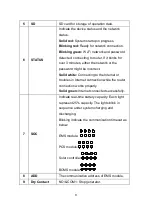
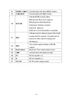
Page 12: ...ssword might be incorrect Solid white Connecting to the Internet or troubles in Internet connection while the router connection works properly Solid green Internet connected successfully 7 SOC Indicate real time battery capacity Each light represent 25 capacity The lights blink in sequence under system charging and discharging Blinking indicate the communication timeout as below EMS module PCS mod...

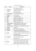
Page 13: ...odule 13 RS485 4 Reserved RJ45 port follow RS485 protocol 14 RS485 1 Reserved RJ45 port follow RS485 protocol 15 CAN Communicate with BCMS module 16 DC 12V DC12V power supply input NOTE Either the USB flash drive or the SD card is provided to the device Removing it will cause the operation data lost 3 PCS Module Figure 4 4 3 PCS Front View ...

Page 14: ...ART A START B Start generator STOP A STOP B Stop generator 9 Synchronizing Signal SYN GND for communication between two NetZeroes 10 DC 12V DC12V power supply output 11 RS485 Communicate with EMS module 12 CAN Communicate with other PCS modules two NetZeroes applied as split phase synchronize in the signal interface 13 STATUS Indicate the power status of PCS module On Power supply is normal Off No...

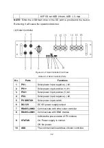
Page 15: ...s Functions 1 PV1 Solar power input negative 1 2 PV1 Solar power input positive 1 3 PV2 Solar power input positive 2 4 PV2 Solar power input negative 2 5 PV SWITCH Solar power input switch 6 DC 12V DC12V power supply output 7 RS485 LINK2 Communicate with other solar controller 8 RS485 LINK1 Communicate with EMS module 9 STATUS Indicate the power status of PV module On Power supply is normal Off No...

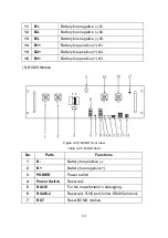
Page 16: ...s positive 2 16 B3 Battery bus positive 3 5 BCMS Module Figure 4 4 5 BCMS Front View Table 4 4 5 BCMS Parts No Parts Functions 1 B Battery bus positive 2 B Battery bus negative 3 POWER Power switch 4 Power Switch Reserved 5 RS232 For the manufacturer s debugging 6 RS485 2 Reserved RJ45 port follow RS485 protocol 7 RST Reset BCMS module ...

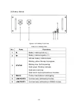
Page 17: ...ly Solid pink Alarming Solid red In device protection or troubles 11 SOC Indicate real time battery capacity Each light represents 25 capacity The lights blink in sequence under system charging and discharging 12 ADD The communication address of BCMS module 13 Dry Contact Reserved Four output and two input 14 LINK Communicate with battery module 15 D DC bus positive 16 D DC bus negative 17 DC 12V ...

Page 18: ... negative 3 STATUS Indicate battery module status Blinking yellow Bootup in progress Blinking blue Self inspecting Solid green Working normally Solid pink Alarming Solid red In device protection or troubles 4 RS232 For the manufacturer s debugging 5 LINK PORT0 Communicate with battery module 6 LINK PORT1 Communicate with battery or BCMS module ...

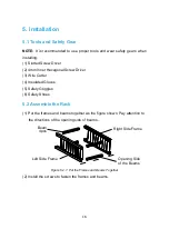
Page 19: ...Driver 3 Wire Cutter 4 Insulated Gloves 5 Safety Goggles 6 Safety Shoes 5 2 Assemble the Rack 1 Put the frames and beams together as the figure shown Pay attention to the directions of the opening side of beams Figure 5 2 1 Put the Frames and Beams Together 2 Install the screws to fasten the frames and beams Beam 4pcs Left Side Frame Right Side Frame Opening Side of the Beams ...

Page 20: ...ounting Part 4 Put the rack where NetZero will be placed and mount it to the floor and wall with anchor bolts if necessary Make sure the rack is horizontal and the front side faces forward Pay attention to the maintenance space requirement for each side Screw M5 8 32pcs Floor Mounting Part 4pcs Screw M8 25 4pcs ...

Page 21: ... 3 Install the Modules 1 Put all the modules into the rack from the front side and then fasten them with screws Figure 5 3 1 Install the Modules Front Side is with Threaded Holes on the Support Surface Maintenance Space Wall Mounting Part 2pcs ...

Page 22: ...Fi Antenna onto the connector as the figure shown Figure 5 3 2 Screw on the Wi Fi Antenna 5 4 Internal Wiring Connect the cables between the modules as the figure shown Figure 5 4 1 Internal Wiring Diagram Wi Fi Antenna ...

Page 23: ...k connectors Solar controller B2 to PCS B1 Solar controller B1 to BCMS D 5 Power cable Black 130mm 4AWG 2 Black Surlok connectors Solar controller B2 to PCS B1 Solar controller B1 to BCMS D 6 Communication cable Black 190mm Standard 8 way Ethernet cable RJ45 connectors BCMS module Link Port to the top battery module Link Port 0 Battery module Link Port 1 to the next battery module Link Port0 below...

Page 24: ...0mm PCS module DC12V to EMS module DC12V 11 DC 12V Power cable 120mm PCS module DC12V to Solar controller DC12V NOTE Keep pressing the lock button when unplug the Surlok connector WARNING Failure to follow the instructions may damage the device 5 5 External Wiring 1 Connect the external cables as the figures shown Figure 5 5 1 Single Phase Example Wiring Diagram ...

Page 25: ...le Wiring Diagram Figure 5 5 3 Example Wire Routing WARNING Generator must be turned off and switch to non remote mode before refueling Failure to follow this instruction may cause fire and explosion Solar Power Wire Communication Wire ...

Page 26: ...ounding and disconnect devices The actual connection depends on your application case Not all the ports are necessary to be connected Please set up the actual value of generator maximum power by the app Refer to the generator user manual for the detail information about how to install connect the remote control cable and how to switch the generator into remote mode Figures below are examples for t...

Page 27: ... to startup Therefore it takes more than 60 seconds for 12 battery packs to be fully started up the BCMS and Battery Module start normally and 2 Switch on the PV SWITCH on the Solar Controller and 3 Switch on the MAIN switch on PCS EMS module WARNING Failure to follow the instructions may damage the device 6 2 ShutDown System 1 Switch off the MAIN switch on PCS module and 2 Switch off the PV switc...

Page 28: ...the device QR code or input the device code to add your devices You can find the QR code and the device code on the label pasted on the device 6 4 Network Connection NOTE The network is not necessary for NetZero But NetZero should be connected to your router if you need to use the app to monitor it Internet is required only if you want to monitor NetZero when you are not at home NetZero can be con...

Page 29: ... on EMS modules are always solid red Table 7 1 Solutions for Troubles 1 Possible Reasons Solutions The device may be crashed or damaged Unplug power supply of DV12 on EMS and re plug in 5 seconds If it cannot recover shut it down and contact us 2 The indicators on EMS modules are always blinking red Table 7 2 Solutions for Troubles 2 Possible Reasons Solutions The Wi Fi is not 2 4G Select a 2 4G W...

Page 30: ... for Troubles 4 Possible Reasons Solutions Something wrong with the router or Internet Check your internet status Reset the router if necessary 5 Failed to start the generator remotely Table 7 5 Solutions for Troubles 5 Possible Reasons Solutions The generator may not work properly Check the generator The remote control cable is disconnected Check and re connect the cable 6 The indicator on BCMS m...

Page 31: ...lutions for Troubles 7 Possible Reasons Solutions The communication cable between BCMS and the battery module may be disconnected Check and re connect the cable Follow the procedures in Chapter 6 2 ShutDown System then Chapter 6 1 Boot System to shut down and reboot BCMS 8 The indicator on BCMS module is solid red and the indicator on one battery module is solid pink or off Table 7 8 Solutions for...

Page 32: ... 6 1 Boot System to shut down and reboot BCMS 10 The indicator on battery module keeps blinking in blue for over 30 seconds Table 7 10 Solutions for Troubles 10 Possible Reasons Solutions Failure in CAN communication Step 1 Reconnect CAN communication line between BCMS and battery module Step 2 Follow the procedures in Chapter 6 2 ShutDown System then Chapter 6 1 Boot System to shut down and reboo...

Page 33: ... pack to a safe area before it catches fire 3 Wet Batteries If the battery pack is wet or submerged in water do not let people access it and then contact POMCube or an authorized dealer for technical support 4 Damaged Batteries Damaged batteries are dangerous and must be handled with the utmost care They are not fit for use and may pose a danger to people or property If the battery pack seems to b...

Page 34: ...nstructions The product was not used for its intended function and environment Any failure or defect arose out of the presence of a third party product or component whether authorized or not Any failure or defect was a result of improper installation or testing misuse neglect unauthorized repair modification accident or other external causes Customer does not provide required proof of purchase POM...

Page 35: ......

Page 36: ..._____________________________________________________________ 2019 POMCube Inc All rights reserved For more information please visit www pomcube com Follow us Facebook Twitter ESS4Residence POMCube Inc ...

Reviews: