background image

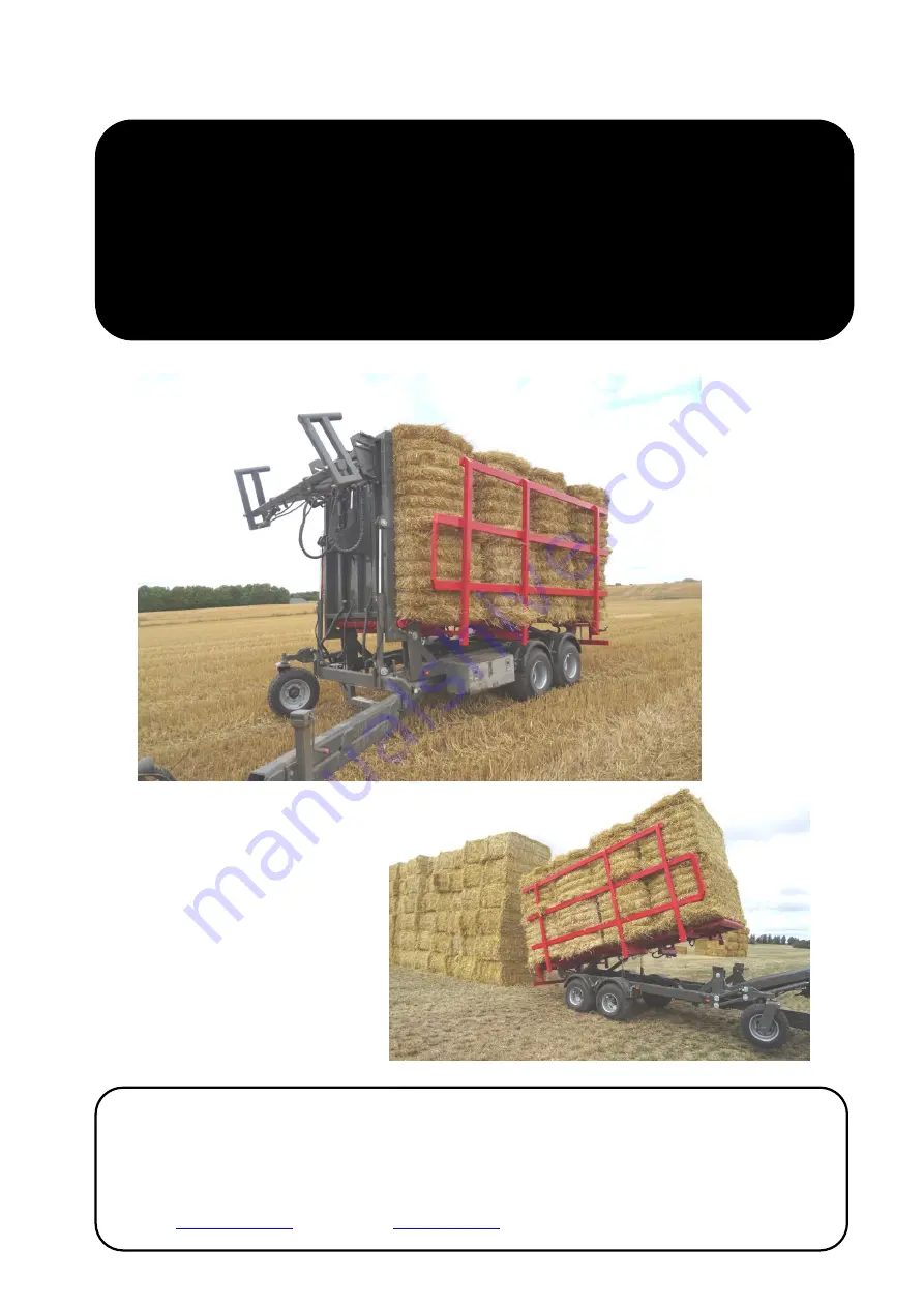
Stack 200 

Instruction Manual 

POMI Industri  ApS 

Abildvadvej 5, Thorup, DK-9610 Norager 
Phone +45 98 55 20 00, 45 40 34 20 10 
E-mail: 

pomi@pomi.dk

   -  Website

www.pomi.dk


English 

Summary of Contents for Stack 200

Page 1: ...1 Stack 200 Instruction Manual POMI Industri ApS Abildvadvej 5 Thorup DK 9610 Norager Phone 45 98 55 20 00 Mobile 45 40 34 20 10 E mail pomi pomi dk Website www pomi dk English ...

Page 2: ...MACHINE IDENTIFICATION 5 5 COMPUTER 6 6 SENSOR OVERVIEW 7 7 BALE STACKER START UP 8 8 THE HYDRAULIC SYSTEM 10 8 1 THE TRAILER VALVE BLOCK 10 8 2 VALVES IN THE CONTROL BOX TOOLBOX 10 8 3 HYDRAULICS DIAGRAM 11 9 ELECTRIC BOX 13 9 1 WIRING DIAGRAM 15 1 TECHNICAL SPECIFICATIONS 22 Revised on 29 05 2019 ...

Page 3: ...achine when it is in operation as the machine can make sudden movements and oil may squirt from a damaged hose The lights must be functioning in accordance with national traffic regulations It is the operator s responsibility to ensure that the lights meet current national legislation Drive sensibly when using the bale stacker as reckless driving will damage the trailer POMI assumes no liability f...

Page 4: ...he machine has been manufactured in conformity with the following national international standards and technical specifications DS EN ISO 12100 1 2005 Safety of Machinery Basic concepts and general principles for design Part 1 Basic terminology and methodology DS EN ISO 12100 2 2005 Safety of Machinery Basic concepts and general principles for design Part 2 Technical principles DS EN ISO 13857 200...

Page 5: ...hine identification When ordering parts please state the serial number of the machine You will find the serial number on the left side of the machine as shown in the picture below Serial no ___________________ ...

Page 6: ...ift the loading platform up and down tip the bales onto the trailer 6 Tilt the trailer 7 Move the stacker forks forward backwards depending on the amount of bales stacked on the trailer 8 Move the drawbar to the right the left 9 Move the support wheel located in the front right corner up down 10 Move the left side in out 11 Move the right side in out 12 Bale push off ...

Page 7: ...7 6 Sensor overview This is an overview of the sensors on the Stack 200 ...

Page 8: ...e bale clamp comes out You use this for turning the bale When pressing the start button a second time the loading program will start By pressing Menu you can switch the program so the bale clamp starts in the outer position Press the start button to start the loading program When the loading program starts the bale clamp compresses the bale until reaching the compression pressure set in the PLC Th...

Page 9: ...the trailer is full It is therefore important to enter in the PLC how many layers and stacks you want to load onto the trailer See the section on the electric box The push off mechanism cannot be used if the trailer is not tipped upwards and sensor B8 is activated The push off mechanism must be pulled in and sensor B6 must be activated before the trailer can be tilted up or down ...

Page 10: ...oil flow when using a load sensing control system LS The pressure control valve 2 is set to 180 bars 8 2 Valves in the control box toolbox When using an LS control system the hex screw 3 must tightened and when not using an LS control system hydraulic circulation it must be loosened 1 2 3 ...

Page 11: ...11 8 3 Hydraulics diagram Left side Right side Drawbar Retention fork Bale push off mechanism Bale clamp master slave system ...

Page 12: ...12 Tilt trailer Tilt loading platform Tilt loading platform Support wheel Bend fork yoke Blocking of suspension ...

Page 13: ...lectric box you set how many layers and stacks you want to load onto the trailer Here you also set the closing and opening time for the bale clamp If you need to change any of the values press and hold the ESC button until a row lights up ...

Page 14: ...s move to the row you want to change and press OK Then there is only one number marked where you can move the selection with the left right arrows and change the value with the up down arrows Press OK and exit by pressing the ESC button ...

Page 15: ...ng diagram Sensor Tilt fork yoke UP Sensor Tilt fork yoke DOWN Sensor Tilt loading platform UP Sensor Tilt loading platform DOWN Sensor Bale push off Sensor Tilt trailer Start Pause Change program Sensor Pressure ...

Page 16: ...16 Bale clamp CLOSE Bale clamp OPEN Bend fork UP Bend fork DOWN Tilt loading platform UP Tilt loading platform DOWN Tilt trailer UP Tilt trailer DOWN Retention fork forward Retention fork backwards ...

Page 17: ...17 Drawbar IN Drawbar OUT Support wheel DOWN Support wheel UP Left side DOWN Left side UP Right side UP Right side DOWN Bale push off mechanism IN Bale push off mechanism OUT ...

Page 18: ...18 Bypass valve Bale clamp CLOSE Bale clamp OPEN Retention fork Retention fork reflux valve Tilt trailer UP Tilt trailer DOWN Tilt trailer UP ...

Page 19: ...19 Tilt loading platform DOWN Bend for yoke Tilt fork yoke UP Bend for yoke Tilt fork yoke DOWN Bale push off mechanism OUT Bale push off ...

Page 20: ...20 Drawbar IN Drawbar OUT Support wheel DOWN Support wheel UP Left side DOWN Left side UP Right side UP Right side DOWN Bale push off mechanism IN Bale push off mechanism OUT Bale push off ...

Page 21: ...21 EMERGENCY STOP ...

Page 22: ...Max hydraulic operating pressure 180 bars Power 12 V Transport width 2 5 meters Operating width 2 7 meters Height 3 9 meters 4 15 meters Length 9 10 meters Weight 6000 kg Max Load 8000 kg Wheels 4 400 60 15 5 Noise level Below 70 dB ...

Reviews: