Automatic boiler for wood pellets
25
5.3
INSTALATION OF THE CERAMIC CATALYTIC REFLECTOR
The ceramic catalytic reflector is manufactured from highly heat-resistant material (1800°C). It has two functions:
- directs the flow of combustion products through the boiler body
- assists very efficiently to burn out carbon substances and thus to reduce considerably harmful substances in
combustion products.
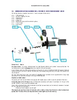
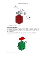
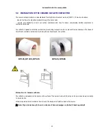
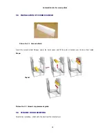
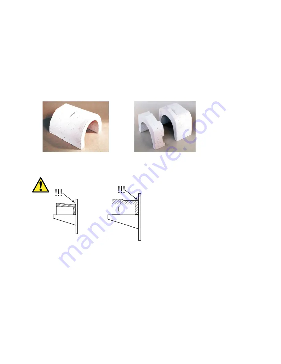
Tne reflector is placed outside the combustion space during transport in order to prevent from any damage. The shape of
the reflector reminds a hollow semi cylinder with one face closed - see picture.
KP 12S, KP 22S, KP 52S KP 62S, KP 82S
Picture No. 18 Ceramic reflector
The reflector is installed into the boiler on the surface of the burner boiler with the stop on its rear side and symmetrically
to its centre line.
While in operation ceramic reflector has to touch the back part of isolation desk of the burner.
Note:
If you do not keep it, there is a chance of burner damage or a Boiler!! Check regularly!!
Summary of Contents for KP 12S
Page 1: ......
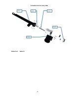
Page 17: ...Automatic boiler for wood pellets 16 Picture No 9 Feeder F1 4 5 1 4 5 2 4 5 3 4 5 4 4 5 5 ...
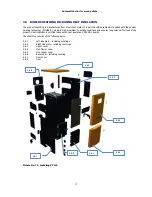
Page 28: ...Automatic boiler for wood pellets 27 Picture No 20 Ceramic grate parts placement guide ...
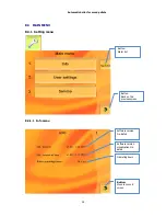
Page 41: ...Automatic boiler for wood pellets 40 8 3 1 2 Menu users settings ...
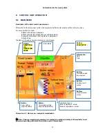
Page 43: ...Automatic boiler for wood pellets 42 Cleaning an ash removing Skin Time window setting ...
Page 46: ...Automatic boiler for wood pellets 45 Actual values Configuration ...
Page 52: ...Automatic boiler for wood pellets 51 Cleaning Ash removing USB Time window setting ...
Page 53: ...Automatic boiler for wood pellets 52 Load from USB Save on USB ...
Page 58: ...Automatic boiler for wood pellets 57 ...
Page 60: ...Automatic boiler for wood pellets 59 ...
Page 61: ...Automatic boiler for wood pellets 60 i ...
Page 63: ...62 Picture No 24 Principle of the modulation ...
Page 64: ...63 Picture No 25 Directory information consumption wood pellets for boiler family KP ...
Page 65: ...64 Picture No 26 Circuit diagram control unit ...
Page 66: ...65 Picture No 27 Circuit diagram module HZS 533 ...
Page 67: ...66 Picture No 28 Circuit diagram HZS 533 HZS 535 ...
Page 73: ...72 11 APPENDIX 2 REPORT ON THE PUTTING THE BOILER KP INTO OPERATION ...
Page 74: ...73 12 APPENDIX 3 SELF ADHESIVE LABEL IMPORTANT SAFETY INFORMATION ...

