Automatic boiler for wood pellets
3
8.3.2.2
Sanitary water ............................................................................................................................ 56
8.3.2.3
Heating circuit ............................................................................................................................ 58
9
GUARANTEE AND LIABILITY FOR DEFECTS ...................................................................................................... 61
10
APPENDIX 1 - TECHNICAL DATA OF THE BOILERS KP X2S................................................................................. 67
10.1
INSTALLATION DIMENSION OF BOILER ................................................................................................. 67
10.2
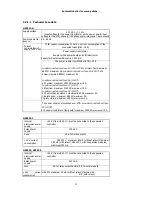
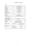
TECHNICAL DATA ................................................................................................................................. 69
11
APPENDIX 2 - REPORT ON THE PUTTING THE BOILER KP INTO OPERATION ...................................................... 72
12
APPENDIX 3 - SELF-ADHESIVE LABEL - IMPORTANT SAFETY INFORMATION ....................................................... 73
PICTURES
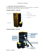
Picture No. 1
Boiler body ................................................................................................................................6
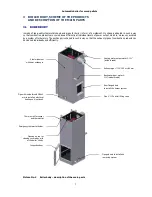
Picture No. 2
Boiler body – description of the main parts .............................................................................7
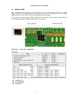
Picture No. 3
Control unit - configuration ......................................................................................................8
Picture No. 4
HZS 521-G Connector and terminal electronics layout ............................................................9
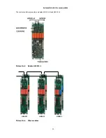
Picture No. 5
Module HZS 532-1.................................................................................................................. 10
Picture No. 6
Other modules ........................................................................................................................ 10
Picture No. 7
Terminal with USB ................................................................................................................. 12
Picture No. 8
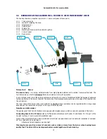
Burner ..................................................................................................................................... 14
Picture No. 9
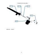
Feeder F1 ................................................................................................................................ 16
Picture No. 10
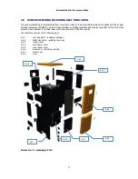
Jacketing KP 12S .................................................................................................................. 17
Picture No. 11
Ash removal system ............................................................................................................. 18
Picture No. 12
Heat exchanger cleaning ...................................................................................................... 19
Picture No. 13
External ash container ......................................................................................................... 19
Picture No. 14
Standard fuel bin sizes ......................................................................................................... 21
Picture No. 15
Assembly guide ..................................................................................................................... 21
Picture No. 16
Required chimney draft ........................................................................................................ 23
Picture No. 17
Burner installation ................................................................................................................ 24
Picture No. 18
Ceramic reflector .................................................................................................................. 25
Picture No. 19
Parts of secondary ceramic grate ........................................................................................ 26
Picture No. 20
Ceramic grate parts placement guide .................................................................................. 27
Picture No. 21
Ceramic shield ...................................................................................................................... 28
Picture No. 22
Ceramic top placement guide .............................................................................................. 28
Picture No. 23
Main menu – sample of visualisation ................................................................................... 37
Picture No. 24
Principle of the modulation .................................................................................................. 62
Picture No. 25
Directory information - consumption wood pellets for boiler family KP ............................ 63
Picture No. 26
Circuit diagram – control unit .............................................................................................. 64
Picture No. 27
Circuit d module HZS 533...................................................................................... 65
Picture No. 28
Circuit diagram - HZS 533, HZS 535 .................................................................................... 66
Summary of Contents for KP 12S
Page 1: ......
Page 17: ...Automatic boiler for wood pellets 16 Picture No 9 Feeder F1 4 5 1 4 5 2 4 5 3 4 5 4 4 5 5 ...
Page 28: ...Automatic boiler for wood pellets 27 Picture No 20 Ceramic grate parts placement guide ...
Page 41: ...Automatic boiler for wood pellets 40 8 3 1 2 Menu users settings ...
Page 43: ...Automatic boiler for wood pellets 42 Cleaning an ash removing Skin Time window setting ...
Page 46: ...Automatic boiler for wood pellets 45 Actual values Configuration ...
Page 52: ...Automatic boiler for wood pellets 51 Cleaning Ash removing USB Time window setting ...
Page 53: ...Automatic boiler for wood pellets 52 Load from USB Save on USB ...
Page 58: ...Automatic boiler for wood pellets 57 ...
Page 60: ...Automatic boiler for wood pellets 59 ...
Page 61: ...Automatic boiler for wood pellets 60 i ...
Page 63: ...62 Picture No 24 Principle of the modulation ...
Page 64: ...63 Picture No 25 Directory information consumption wood pellets for boiler family KP ...
Page 65: ...64 Picture No 26 Circuit diagram control unit ...
Page 66: ...65 Picture No 27 Circuit diagram module HZS 533 ...
Page 67: ...66 Picture No 28 Circuit diagram HZS 533 HZS 535 ...
Page 73: ...72 11 APPENDIX 2 REPORT ON THE PUTTING THE BOILER KP INTO OPERATION ...
Page 74: ...73 12 APPENDIX 3 SELF ADHESIVE LABEL IMPORTANT SAFETY INFORMATION ...


