background image

Automatic boiler for wood pellets 


2


STRUCTURAL DESCRIPTION OF PRODUCTS 

The structure adheres to the standard EN 303.5 / 2000 i.e. boilers  for central heating - part 5 (boilers for 

central heating with automatic fuel feed of rated heat output up to 300 kW).  
 

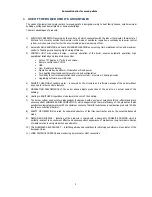
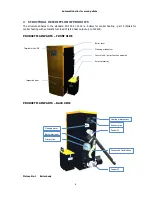
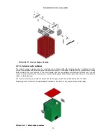
PRODUCT MAIN PARTS – FRONT SIDE 


PRODUCT MAIN PARTS – BACK SIDE 


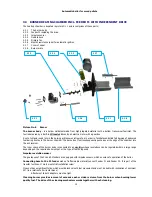
Picture No. 1  Boiler body 


Control unit – boiler function modules 

External ashtray 

Connection flexible hose 

Primary fan 

Boiler cover 

Terminal with USB 

Cleaning mechanism 

Inspection door 

Cleaning motor 

Feeder F2 

Exhaust pipe 

Heating water output 

Feeder F1 

Backwater input 

Summary of Contents for KP 12S

Page 1: ......

Page 2: ...the controls which generally apply in the smoke control area The Secretary of State for Environment Food and Rural Affairs has powers under the Act to authorise smokeless fuels or exempt appliances for use in smoke control areas in England In Scotland and Wales this power rests with Ministers in the devolved administrations for those countries Separate legislation the Clean Air Northern Ireland Or...

Page 3: ...4 3 2 Venting 22 4 3 3 Fire regulations 23 4 3 4 Electrical 23 4 3 5 Protection against noise 23 4 4 STORAGE OF FUEL 23 4 5 BOILER ROOM VENTILATION 23 5 PUTTING THE PRODUCTS INTO OPERATION 24 5 1 CONNECTION TO THE SYSTEM 24 5 2 INSTALLATION OF THE BURNER 24 5 3 INSTALATION OF THE CERAMIC CATALYTIC REFLECTOR 25 5 4 INSTALLATION OF SECONDARY CERAMIC GRATE 26 5 5 INSTALLATION OF CERAMIC SHIELD 28 5 6...

Page 4: ...ture No 8 Burner 14 Picture No 9 Feeder F1 16 Picture No 10 Jacketing KP 12S 17 Picture No 11 Ash removal system 18 Picture No 12 Heat exchanger cleaning 19 Picture No 13 External ash container 19 Picture No 14 Standard fuel bin sizes 21 Picture No 15 Assembly guide 21 Picture No 16 Required chimney draft 23 Picture No 17 Burner installation 24 Picture No 18 Ceramic reflector 25 Picture No 19 Part...

Page 5: ...e 8 If any work which generates inflammable vapours takes place in the boiler room glueing the floor etc the boiler has to be out of operation and the fire has to be burnt out in the boiler 9 Having the heating season been finished clean the boiler thoroughly as per the chapter Maintenance Products of combustion stuck to the walls of the exchanger may act corrosively for the whole period of time w...

Page 6: ... or solar system maximum 7 heating circuits Upgrading software over USB stick 4 PRIORITY HEATING of sanitary water is secured by the structure and software package of the boiler without any need for other control elements 5 MODULATION PERFORMANCE of the boiler allows adjusts production of the heat to an actual need of the building 6 Heating in EQUITHERM regulation mode lowers the cost of the heati...

Page 7: ...ting with automatic fuel feed of rated heat output up to 300 kW PRODUCT MAIN PARTS FRONT SIDE PRODUCT MAIN PARTS BACK SIDE Picture No 1 Boiler body Control unit boiler function modules External ashtray Connection flexible hose Primary fan Boiler cover Terminal with USB Cleaning mechanism Inspection door Cleaning motor Feeder F2 Exhaust pipe Heating water output Feeder F1 Backwater input ...

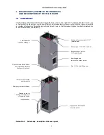
Page 8: ...e exhaust pipes of combustion products can be cleaned individually and efficiently Picture No 2 Boiler body description of the main parts Steel weldment with heat exchanger Inspection door Exhaust pipe 130 150 or 160 mm Heating water output water G 1 inside thread Backwater input water G 1 inside thread Rear flanged hole to install the burner system Pipe G to install filling valve Pipe with inside...

Page 9: ... configuration Picture No 3 Control unit configuration Configuration Name Type Options Order code Control unit boiler function module HZS 521 G Standard Terminal touchscreen HZS 555 S Standard Module extension HZS 532 1 Standard Module heating circuit accumulation tank HZS533 Optional Module solar HZS535 Optional Type and number of circuit Type and number of module HC1 SWT HZS 521 G HZS532 1 HC1 H...

Page 10: ...m All interfaces and connections for controlling of the boiler are located on the control board Picture No 4 HZS 521 G Connector and terminal electronics layout Ambient temperature sensor HC1 mix temp Backwater temp Sanitary water temp Exhaust temp Sanitary water top Sanitary water bottom Room thermostat 3 Room thermostat 2 SWT thermostat Room thermostat 1 Impulse sensor 2 Impulse sensor 1 Room th...

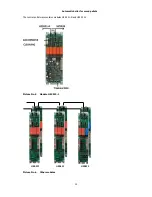
Page 11: ...Automatic boiler for wood pellets 10 The control unit always contains modules HZS 521 G and HZS 532 1 Picture No 5 Module HZS 532 1 HZS533 HZS533 HZS535 Picture No 6 Other modules ...

Page 12: ... A Loads connected over fuse F7 10 AT X8 Ignition maximum 2300 W maximum 10 A Loads connected over fuse F8 10 AT X5 heat exchange cleaner maximum 690 W maximum 3 A X6 grate open maximum 690 W maximum 3 A X7 grate closed maximum 690 W maximum 3 A The power supply not switched over STB L Loads connected over fuse F9 10 AT X10 boiler circuit return flow pump maximum 2300 W maximum 10 A HZS532 1 Inter...

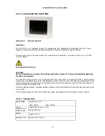
Page 13: ...reen can only be cleaned with a soft damp cloth To dampen the cloth a screen cleaning solution such as antistatic foam water with detergent or alcohol should be used First spray the cleaning fluid on the cloth and not directly on the terminal The cleaning solution should not be allowed to reach the terminal electronics for example through the ventilation slots No erosive cleaning solutions chemica...

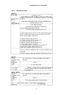
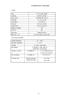
Page 14: ...ghting LED Contrast 600 Brightness Typically 350 cd m Angle CR 10 Left right below 75 above 60 Environmental conditions Storage temperature 10 85 C Operating temperature 0 50 C Humidity 10 90 uncondensed EMV stability EN 61000 6 2 noise immunity EN 61000 6 4 noise emission Vibration tolerance EN 600068 2 6 2 9 Hz Amplitude 3 5 mm 9 200 Hz 1 g 10 m s Shock resistance EN 60068 2 27 15 g 150 m s Prot...

Page 15: ...el is subsequently pushed over the edge of the chamber into the ash receiver The inner space of the burner body is connected to an air fan whose revolutions can be regulated within a large range depending on the required boiler output or the type of fuel being used Impulse revolution sensor The gearboxes of the F1 and F2 feeders are equipped with impulse sensors which ensure safe operation of the ...

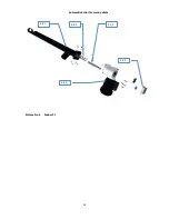
Page 16: ...See cap 5 3 5 6 3 5 FEEDER F1 WITH INDEPENDENT DRIVE FROM FUEL STORAGE F1 feeder delivers fuel from fuel storage to the burning chamber It comprises of a pipe delivery path with an overflow part and an end sleeve The feeder is built into the fuel storage under an angle which cannot exceed 45º If the angle was any bigger fuel could be dispensed inaccurately The transporter has its own electric driv...

Page 17: ...Automatic boiler for wood pellets 16 Picture No 9 Feeder F1 4 5 1 4 5 2 4 5 3 4 5 4 4 5 5 ...

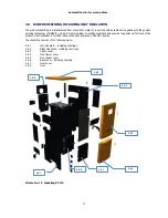
Page 18: ...onditions and ensures long term perfect look of the product Heat insulation 8 cm thick is done with heat insulation ROCKWOL boards The sheathing consists of the following parts 4 6 1 Left side plate including coverings 4 6 2 Right side plate including coverings 4 6 3 Upper cover 4 6 4 Front lower cover 4 6 5 Front upper cover 4 6 6 Back cover including covering 4 6 7 Door cover 4 6 8 Door Picture ...

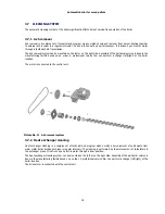
Page 19: ...an order A professional service firm can perform a change left right at the boiler location The motor is connected to the control unit 3 7 2 Heat exchanger cleaning Heat exchanger cleaning is a complex set of technical and program means which ensure removal of solid waste from warm water boiler exchanger pipes in regular intervals The cleaning is performed by linear movement of turbulators in the ...

Page 20: ...ver must be in the lower position and the connecting piping between the boiler and the ash receiver must be tight Also the receiver cover must be tightly closed Both of these requirements prevent burning fumes release to the boiler room The receiver is removed by moving the detent lever to the upper position and pulling it away from the boiler Dispensing of the contents to the waste disposal conta...

Page 21: ...rol of another three loops circulatory pump GSM modem for remote control and monitoring of boiler operation Module for boiler connection to Ethernet communication network Internet Outside temperature sensor for equithermal regulation Surface temperature sensor in the fuel intake area Surface temperature sensor temperature measuring behind the mixing valve Surface temperature sensor temperature mea...

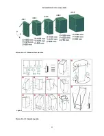
Page 22: ...Automatic boiler for wood pellets 21 Picture No 14 Standard fuel bin sizes Chyba Picture No 15 Assembly guide ...

Page 23: ... relation to the electrical network it is necessary to ensure that the wall socket where the boiler is connected is always accessible 4 3 LEGISLATION IN FORCE Installed system is able to meet the installation requirements of Building Regulations in Northern Ireland 2010 No 382 Installed system is able to meet the installation requirements of Building Regulations in Wales The Building Regulations 2...

Page 24: ...2 2007 Safety Part 2 102 Special requirements for appliances burning gas petroleum and solid fuels containing electrical connections 4 3 5 Protection against noise Government Regulation no 148 2006 Coll product is fulfilling all requirements 4 4 STORAGE OF FUEL Wood pellets have to be in a dry place protected against atmospheric effects because humidity damages the aggravates their burning paramet...

Page 25: ...and this tension may cause damage to the homogeneity of the body Attention Impurities and sediments which might jeopardize failure free operation of pumps have to be thoroughly rinsed before the system is finally filled with water 5 2 INSTALLATION OF THE BURNER The burner of the boiler is configured into one unit the body of the burner screw feeder gear unit motor 2 spirals for electric ignition i...

Page 26: ...ne reflector is placed outside the combustion space during transport in order to prevent from any damage The shape of the reflector reminds a hollow semi cylinder with one face closed see picture KP 12S KP 22S KP 52S KP 62S KP 82S Picture No 18 Ceramic reflector The reflector is installed into the boiler on the surface of the burner boiler with the stop on its rear side and symmetrically to its ce...

Page 27: ...s of the gaseous combustible on the ceramic burning surface direct the flow of combustion products through the exchanger Installation of grate in to working surface is done through cleaning door of the boiler Individual parts have to lift in the angle and place in back part of the burning chamber upwards After is pushed all the way up to ceiling of a burning chamber the front side of the ceramic h...

Page 28: ...Automatic boiler for wood pellets 27 Picture No 20 Ceramic grate parts placement guide ...

Page 29: ...the ceramic shield flatways across the boiler space and fit the part on holders over the door from inside Steps Picture No 22 Ceramic top placement guide 5 6 CERAMIC DOOR JACKETING Ceramic door jacketing attached to the door from the manufacturer Picture No 21 Ceramic shield Chyba ...

Page 30: ...by qualified personnel only Connect the particular appliances according with connection diagram During connecting the equipment must be shut down with the main switch or disconnected from power supply by pulling the electric cord from the outlet 1 Relay for electric ignition 2 Burner thermostat 3 Cover control unit 4 2x M4 5 Boiler thermostat 6 Control unit ...

Page 31: ...d personnel F1 feeder motor function and correct rotation direction F2 feeder motor function and correct rotation direction Correct functioning of F1 feeder impulse sensor and simultaneously Correct functioning of F2 feeder impulse sensor Functioning of fan and linearity of its regulation Functioning of flue fan and linearity of his regulation if used Functioning of system pump and its venting Fun...

Page 32: ...cal Authority Building Notice When flue or chimney is provided as part of the installation the installer must provide information essential to its correct application with permanently displayed way 6 BOILER SERVICE AND MAINTANANCE DURING OPERATION Service and maintenance intervals are directly dependent on the type and quality of used fuel If recommended fuel wood pellets with clearly guaranteed q...

Page 33: ...er each visual check of burning or after ash removal you must always make sure that the boiler door is tightly closed to avoid being stricken by flames from the burning chamber Ajar or slightly opened door will cause increased fire hazard and also negatively affect the fuel burning processes 6 1 3 Flue gases exchanger cleaning Cleaning of the gas flue is done automatically in intervals set by the ...

Page 34: ...cleaning The ceramic grate construction has a self cleaning feature Dust particles do not stick to the grate after burning pellets Nevertheless check cleanliness of these parts If needed you can get rid of the dust particles by slightly shaking the individual parts of the ceramic grate After this procedure check correct placement of ceramic parts Anticipated intervals inspection once every 4 month...

Page 35: ... down and remove the part out Now remove all ash build ups by steel brush from ceramic parts Note Do not forget that all parts are made of ceramic Work carefully so you do not damage all parts Cleaning the draughts of combustion products If there is automatic cleaning installed there just has to remove a dust above exchanger by a vacuum cleaner or by forfeiture dust through pipes of heat exchanger...

Page 36: ...ange fits tightly on the protruding ribs of the body all over the circumference The spiral chute feeder should be anchored precisely in the axis of the pipe and should not thus drag against the wall of the pipe which is one of reasons why smooth operation is blocked The joint has to be treated with a sealing paste before the flange of the drive is installed which is an important measure against sm...

Page 37: ...ith sensing and control elements is subjeck to return collection Return collection takes place in seller s plant where was this product purchased or at the manufacturer of the boiler Return collection is free of charge In accordance with current requirements of environmental protection the electronic parts of the poduct does not contain lead Still do not dispose el equipment as a municipal waste 7...

Page 38: ...time The data are showed as numbers diagrams or combination Picture No 23 Main menu sample of visualisation Note Changes important parameters for combustion quality and safety is allowed after insert password according with table No 6 In the end of this manual Button Information and Service menu Button Heating circuit setting Button Move to second screen Button SELECTION OF OPERATING MODE Actual s...

Page 39: ...oiler is normally working Stand by Quiet mode of the boiler when the boiler is not burning actively Boiler is ready on the basis of impulse from surrounding equipment thermostats GSM Modem to restore the supply of heat Note Change SELECTION OF OPERATING MODE is possible to make at any time during operation Note If boiler is working in MODULATION or EQUITHERM control unit automatically setting powe...

Page 40: ... pellets 39 8 3 MAIN MENU 8 3 1 Setting menu 8 3 1 1 Info menu Button Back on the previous screen Button Alarm list Software version No dated Software version visualisation No dated Operating hours Button Move to second screen ...

Page 41: ...Automatic boiler for wood pellets 40 8 3 1 2 Menu users settings ...

Page 42: ...rent time HH MM SS Current date DD MM YY Tine without screensaver Button Password Showed Please insert your password After touch on the box for password Insert password and enter In the end confirm OK If is password right button change on green colour ...

Page 43: ...Automatic boiler for wood pellets 42 Cleaning an ash removing Skin Time window setting ...

Page 44: ...pellets 43 IP Adress 8 3 1 3 Menu Service Button Password Showed Please insert your password After touch on the box for password Insert password and enter In the end confirm OK If is password right button change on green colour ...

Page 45: ...r turn on Feeders 1 Feeder F2 2 Feeder F1 The rotation is signalized by two small red windows blinking When fuel is falling down from Feeder F1 into Feeder F2 immediately stop Feeders Overfilling of fuel is dangerous Other functionality are used for diagnosing of functionality Button Password Showed Please insert your password After touch on the box for password Insert password and enter In the en...

Page 46: ...Automatic boiler for wood pellets 45 Actual values Configuration ...

Page 47: ...ality correct function and safety The producer saves changes of parameters by password Is prohibited to make unqualified changes Important note The value of parameters on the pictures below is ONLY SAMPLES Actual setting depend on the type of boiler Producer and qualified service can make changes only Next page ...

Page 48: ...7 Next page Temperatures Previous page Maximum boiler temperature Minimum exhaust temperature for heating Button for activate electric heating Maximum exhaust temperature Temperature for activate pump Temperature for activate bypass pump ...

Page 49: ...ime for pre heating of ignition spiral without fan Control temperature Note Control temperature is important for fire control Fan revolution Time limit for ignition Time for stabilisation of fire Fuel for stabilisation of fire Time spiral activation during stabilisation of fire Time for prolong of stabilisation of fire Time feeder F1 during burn on fuel ...

Page 50: ... to select programs for settings Parameters for chosen program above Actual program for fix power Note Is possible to set here but main settings is on the main menu Time period in which automatic boiler is not actively burning Time fire life Setting temperature Time ...

Page 51: ...ellets 50 Modulation Feeders Note If it is set 0 then there is no control of the motor PID regulation recommended Parameters for regulations Time count impulses Allowed errors On time feeder F2 before F1 Off time feeder F2 of F2 ...

Page 52: ...Automatic boiler for wood pellets 51 Cleaning Ash removing USB Time window setting ...

Page 53: ...Automatic boiler for wood pellets 52 Load from USB Save on USB ...

Page 54: ...Automatic boiler for wood pellets 53 8 3 2 Menu heating circuits Button for open window for addition heating circuits Button for confirmation ...

Page 55: ...atic boiler for wood pellets 54 After confirmation 8 3 2 1 Tank Demand for heating Time window setting Button for settings menu Button for manual functionality Visualisation of pump status Green On Grey Off ...

Page 56: ...Automatic boiler for wood pellets 55 Function for settings of parameters Function for manual control of pump ...

Page 57: ...r for wood pellets 56 8 3 2 2 Sanitary water Demand for heating Blue heating Red not heating Time window setting Button for settings menu Button for manual functionality Visualisation of pump status Green On Grey Off ...

Page 58: ...Automatic boiler for wood pellets 57 ...

Page 59: ...for heating Blue heating Red not heating Time window setting Button for settings menu Button for manual functionality Visualisation of pump status Green On Grey Off Button for ekviterm parameters Servo location White closed Black opened Servo control White Off Green On ...

Page 60: ...Automatic boiler for wood pellets 59 ...

Page 61: ...Automatic boiler for wood pellets 60 i ...

Page 62: ...e fuel must be approved by the boiler manufacturer 3 If the user wants to claim any form of guarantee he she has to submit duly filled in letter of guarantee number 2 4 The user is obliged to demonstrate that the product was maintained in regular intervals which are described in the chapter MAINTENANCE Regular annual maintenance has to be done by trained person who is also responsible for the reco...

Page 63: ...62 Picture No 24 Principle of the modulation ...

Page 64: ...63 Picture No 25 Directory information consumption wood pellets for boiler family KP ...

Page 65: ...64 Picture No 26 Circuit diagram control unit ...

Page 66: ...65 Picture No 27 Circuit diagram module HZS 533 ...

Page 67: ...66 Picture No 28 Circuit diagram HZS 533 HZS 535 ...

Page 68: ... OF BOILER Type Picture No KP 11 1 KP 11 1 1 KP 12 4 KP 12S 7 KP 21 2 KP 22 5 KP 22S 8 KP 51 3 KP 52S 9 KP 61 6 KP 62 6 KP 62S 10 KP 82 11 KP 82S 11 Legeng KP xxx 1 Water output G 1 1 2 2 Flue ducting Ømm by type KP 3 Water input G 1 1 2 4 Outlet valve G 1 2 5 Semiautomatic cleaning ...

Page 69: ...KP 12 4 KP 12S 7 KP 21 2 KP 22 5 KP 22S 8 KP 51 3 KP 52S 9 KP 61 6 KP 62 6 KP 62S 10 KP 82 11 KP 82S 11 Legeng KP xxx 1 Water output G 1 1 2 2 Flue ducting Ømm by type KP 3 Water input G 1 1 2 4 Outlet valve G 1 2 5 Semiautomatic cleaning ...

Page 70: ...emissions at nominal power g hour 1 0 36 0 65 2 2 Flue gas mass flow rate at nominal power kg sec 0 009 0 009 0 009 0 016 0 016 0 028 0 028 0 035 0 048 Flue gas mass flow rate at minimal power kg sec 0 003 0 003 0 003 0 007 0 007 0 012 0 012 0 015 0 021 Technical parameters of products Parameter Unit KP11 1 KP11 KP 12S KP21 KP 22S KP51 KP52S KP 62S KP 82S Weight kg 255 255 310 335 370 495 520 590 ...

Page 71: ...0 kg filled from tank Electrical parameters of products Parameter Unit KP11 1 KP11 KP 12S KP21 KP 22S KP51 KP52S KP 62S KP 82S Mains voltage 230 V AC 10 50 Hz 2 Hz Standby power consumption W 4 4 4 4 4 4 4 4 4 Standart power consumption 2 motors fan W 173 173 173 193 210 193 210 340 400 Maximal power consumption W 1300 1300 1300 1300 1300 1300 1300 1300 1300 Average power consumption W 212 212 212...

Page 72: ... ppm 98 64 98 41 98 41 103 33 103 33 130 63 130 63 110 45 119 61 Dust mp m3 34 24 32 6 32 6 40 19 40 24 48 32 48 32 40 24 18 24 CO mg m3 O2 10 68 338 49 277 49 277 167 439 167 439 9 108 9 108 137 606 180 451 OGC mg m3 O2 10 8 6 1 3 1 3 4 17 4 27 1 6 1 6 1 10 3 9 NOx mg m3 O2 10 162 138 166 132 166 132 171 121 171 121 188 144 188 144 173 121 190 147 Dust mg m3 O2 10 28 25 27 9 27 11 32 38 32 38 34 ...

Page 73: ...72 11 APPENDIX 2 REPORT ON THE PUTTING THE BOILER KP INTO OPERATION ...

Page 74: ...73 12 APPENDIX 3 SELF ADHESIVE LABEL IMPORTANT SAFETY INFORMATION ...

Reviews: