Workbook 4
Controller SIGMATEK - Boiler control
11
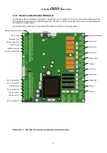
Connect:
Connection terminal
Feeder motor F2
X14- L, N, PE
Impulse sensor F2
X45
Electric ignition spiral
X4-L, N, PE
Primary Fan
X11-L, N, PE
Flue Fan (if used)
X12-L, N, PE
Feeder motor F1
X13- L, N, PE
Impulse sensor F1
X44
Flue thermometer
X31
System pump
X10-L, N, PE
Boiler pump
X7-L, N, PE
Servo 3 (4) – way valve
X5-L, N, PE, X6-L, N, PE
Room thermostat
X46
Boiler thermostat
X47
Outside temperature
X34
Thermometer behind 3 (4) – way valve
X28
Thermometer back water
X29
Important note:
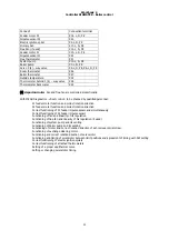
Fan and flue fan are controlled proportionally.
With MENU Diagnostics -
direct control
- to be checked by qualified personnel:
F1 feeder motor function and correct rotation direction
F2 feeder motor function and correct rotation direction
Correct functioning of F1 feeder impulse sensor and simultaneously
Correct functioning of F2 feeder impulse sensor
Functioning of fan and linearity of its regulation
Functioning of flue fan and linearity of his regulation (if used)
Functioning of system pump and its venting
Functioning of boiler pump and its venting
Functioning of motor and correct rotation direction of ash removal spiral screw
Functioning of exchange cleaning motor
Functioning and correct rotation direction of servomotor
Functioning and timing of servomotor between limit positions and agreement of timing with SW setting
Correct functioning of electric ignition spirals
Correct functioning of attached thermometers
Setting of a proper equithermal curve
Setting or changing servomotor timing
Summary of Contents for Sigmatek
Page 1: ......
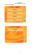
Page 16: ...Workbook 4 Controller SIGMATEK Boiler control 15 3 3 1 2 Menu users settings ...
Page 21: ...Workbook 4 Controller SIGMATEK Boiler control 20 Actual values Configuration ...
Page 28: ...Workbook 4 Controller SIGMATEK Boiler control 27 Load from USB Save on USB ...
Page 33: ...Workbook 4 Controller SIGMATEK Boiler control 32 ...
Page 35: ...Workbook 4 Controller SIGMATEK Boiler control 34 ...
Page 36: ...Workbook 4 Controller SIGMATEK Boiler control 35 i ...
Page 38: ...37 Picture No 7 Circuit diagram control unit ...
Page 39: ...38 Picture No 8 Circuit diagram module HZS 533 ...
Page 40: ...39 Picture No 9 Circuit diagram HZS 533 HZS 53 ...

