


The appliance is not intended for use by persons (including children) with reduced physical,
sensory or mental capabilities, or lack of experience and knowledge, unless they have been
given supervision or instruction concerning use of the appliance by a person responsible for
their safety.
Children should be supervised to ensure that they do not play with the appliance.
For safety reasons, servicing or repair of this item should only be carried out by pondXpert.
Never hang or carry the pump by the power cord.
Do not operate the pump with a damaged cord or plug. The supply cord of the appliance
cannot be replaced.
If the electrical cord is damaged the product should be scrapped.
Safety and Electrical Connections
This unit is designed for outdoor use only. It is waterproof and should be situated safely
under the pond water. Ideally the pump should be situated at the bottom of the pond as this
is where fish waste and debris collects. Take care to ensure that you can easily lift your
pump out of the water for routine maintenance. If this is necessary do not pick your pump up
by the electrical cable but by the main body/ cage of the pump.
Always disconnect all equipment in the pond before starting to handle, maintain, repair or
install any pond equipment.
The pump is electrically operated so great care must be taken during installation and
operation. The following electrical and safety guidelines must be carefully followed.
Each pump is supplied with a 10 metre length of 3 core electrical cable which is
permanently connected to the pump.
The termination to the mains supply should be permanent, inside a dry weatherproof
enclosure, through a double pole switched fused spur with a minimum contact gap of 3mm –
(disconnected) to BS 3676 – and fitted with a 3 or 5 amp fuse.
Exposed cable runs should be sensibly positioned, and protected if necessary by armoured
conduit.
A 10mA or 30mA Residual Current Circuit Breaker (RCD) MUST be fitted to the mains
supply.
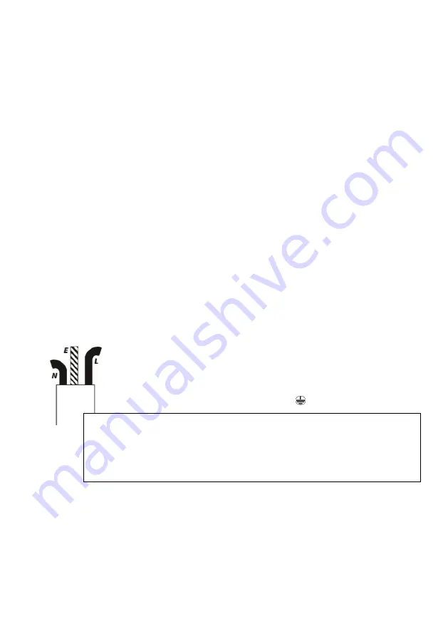
The wires in the mains electrical lead are coloured in accordance with the
following code:
BLUE – Neutral (marked with an “N” in most terminal connections)
BROWN – LIVE (marked with an “L” in most terminal connections)
GREEN/YELLOW – EARTH (marked “E” or in most terminal connections)
1
st
January 2005 revised Building Regulations for England and Wales
Installing this product in the garden is classified as ‘notifiable’. The Regulations
now require you to tell your local authority building control department that you
intend to install this product before installation. Your local authority will let you
know how you can get your installation approved


