PONNDORF Gerätetechnik GmbH
Leipziger Strasse 374
D - 34123 Kassel
Operation Manual
Hose Pump Series
P_delta / PD-S
Page 14 of 29
Version 003_GB / 04.2021
5.2
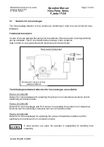
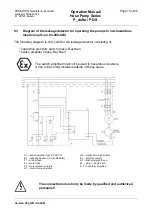
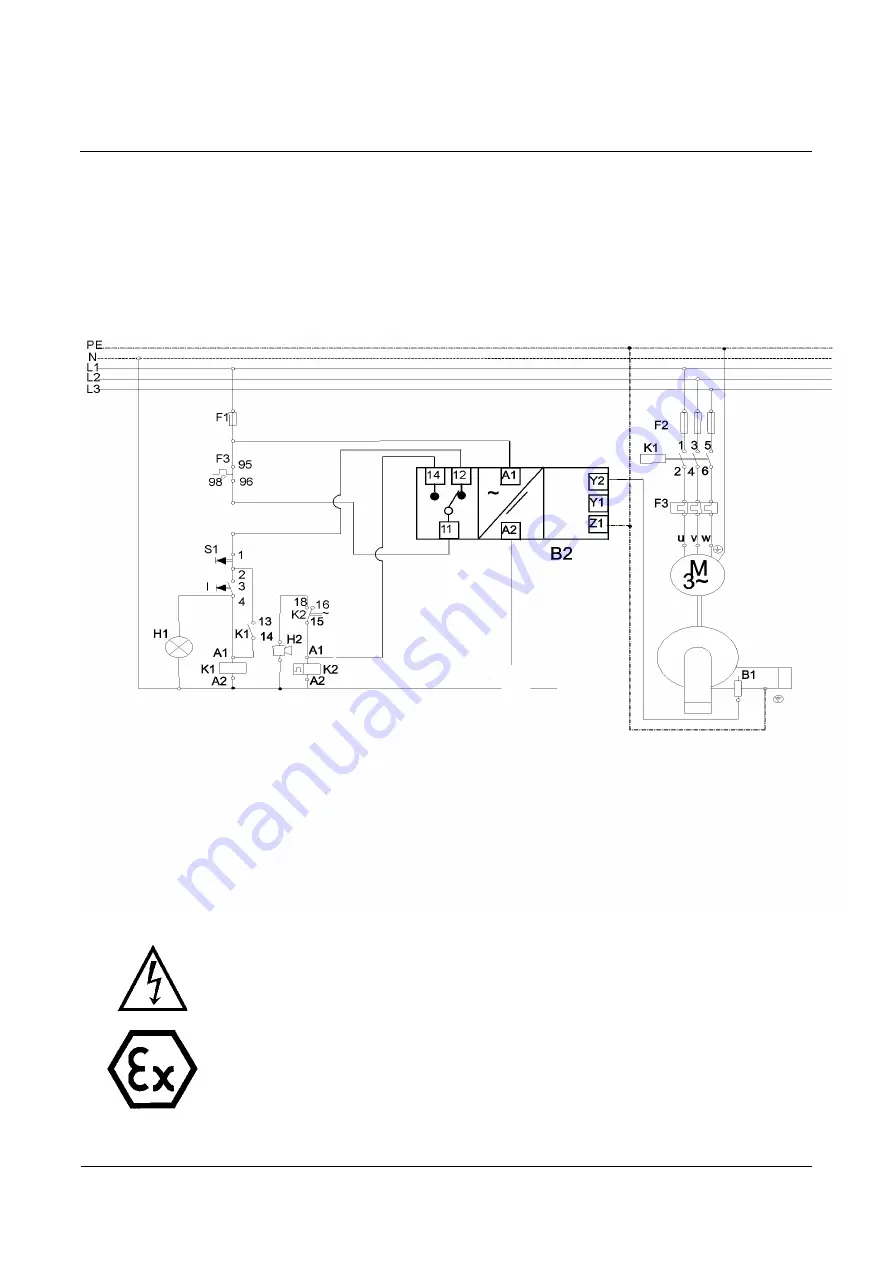
Diagram of the leakage detector for operating the pumps in non-hazardous
locations (art.-no. 93-000-055)
The following diagram is only valid for the leakage detector consisting of:
• sensor for leakage detector (make Ponndorf, standard)
• switch amplifier (make: Disibeint, type DNSA)
The connections must only be made by qualified and authorized
personnel!
The standard detector for hose leakages is not suitable for use in
hazardous locations and non-conductive media.
drive
pump
B2 = Level control, type DNSA
B1 = sensor
F1 = fuse
F2 = motor fuse
F3 = motor overloads
H1 = run light
H2 = signal horn, signal lamp
K1 = motor contactor
K2 = flasher (0,5 sec.)
M
= motor (pump drive)
S1 = push button
Summary of Contents for P delta 15
Page 1: ...Hose Pump Series P_delta PD S Operation Manual...
Page 2: ......


