background image

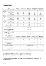
Technical data 


Model 

POOLEX 35

POOLEX 48

POOLEX 65

POOLEX 85 

POOLEX 120 

Heating 

Capacity(W) 

3531 4810 6527 8520  12025 

Heating Input(W)   

699 

963 

1300 

1673 

2414 

Normal 

Current(A) 


3.20 4.41 5.95 7.66  11.05 

[1] 

COP 

5.05 4.99 5.02 5.09  4.98 

Heating 

Capacity(W) 

3249 4415 6003 7938  10998 

Heating Input(W)   

664 

931 

1247 

1612 

2389 

Normal 

Current(A) 


3.04 4.26 5.71 7.38  10.93 

[2] 

COP 

4.89 4.74 4.81 4.92  4.60 

Cooling 

Capacity(W) 

2450 3360 4680 5930  8920 

Cooling 

Input(W) 

780  1060 1520 1870  2860 

Normal 

Current(A) 

3.57 4.85 6.96 8.56  13.09 

[3] 

EER 

3.14 3.17 3.08 3.17  3.12 

Max Current(A) 

5.7 

7.8 

10.0 

14.0 

20.0 

Power Supply 

230V

50Hz 

SETTING TEMPERATURE 

RANGE 

15

℃~

40


RUNNING TEMPERATURE 

RANGE 

-5

℃~

43


UNIT DIMENSIONS     

W×H×D(mm) 

715x565x290

715x565x290

930x630x350

930x630x350 930x630x350 

Net 

Weight 

(KG) 

37 39 47 50  57 

OPERATING NOISE dB(A) 

51 

51 

52 

52 

54 

WATER INLET/OUTLET 

DIMENSION 

2


2


2


2


2


Water Heat Exchanger 

Titanium PVC Tank 

MIN.WATER 

FLOW 

(L/MIN) 

35 35 40 60  80 

PEFRIGERANT R410A 

Display LCD 

MODE Heating/Cooling/AUTO 


[1] Ambient air temperature 24

(DB)/19

(WB), water temperature 20

[2]Ambient air temperature 15

(DB)/12

 (WB), water temperature 13

[3]Ambient air temperature 35

(DB)/27

 (WB), water temperature 27

.


The above data might change as the product improves; please refer to the details on the 
product nameplate. 


4

Water 20

Air 24  /

Water 13

Air 15

/

Water 27

Air 35

/

ENGLISH

Summary of Contents for jetline 120

Page 1: ...Manuals in order ENGLISH FRANCAIS ITALIANO ESPAGNOL...

Page 2: ......

Page 3: ...nt Electric connection 9 Controller instruction 12 Maintenance Troubleshooting 15 Limited warranty 16 1 Installation 6 Sound pressure level 8 Unit dimension 5 Technical data 4 Safety Precautions 3 ENG...

Page 4: ...a plate to make sure you have the proper model before installing The information in this manual was prepared to assist in the proper installation operation maintenance and service of your new heat pum...

Page 5: ...utdoor unit may drop and cause a casualty Make sure that the electric leakage protection switch is fixed If no electric leakage protection switch is fixed at the beginning of the electric supply it ma...

Page 6: ...7 8 10 0 14 0 20 0 Power Supply 230V 50Hz SETTING TEMPERATURE RANGE 15 40 RUNNING TEMPERATURE RANGE 5 43 UNIT DIMENSIONS W H D mm 715x565x290 715x565x290 930x630x350 930x630x350 930x630x350 Net Weight...

Page 7: ...et Water inlet Water outlet Water outlet Unit dimensions Unit dimensions NO A B C D E POOLEX 35 POOLEX 48 POOLEX 65 POOLEX 85 POOLEX 120 565 715 290 313 500 565 630 715 850 290 300 313 313 500 530 630...

Page 8: ...neighboring buildings and the exhaust air cannot flow back Moreover adequate service clearance should be kept around the unit 5 The unit should not be installed at places accompanied with oil inflamma...

Page 9: ...pump unit has auto antifreeze program When the unit is working normally there will not be freezing 2 When the ambient temperature is minus and the unit stops for over 3 hours or the unit stops long te...

Page 10: ...the least sound sensitive neighbouring area The sound pressure levels are further affected by walls bricks differences in ground level etc and should therefore only be seen as guide values 10m 4m 1m S...

Page 11: ...t least a 3 mm breaking gap Incoming supply must be 220 240 V 1 phase neutral ground via a distribution board with fuses If an insulation test is to be carried out in the building please make sure to...

Page 12: ...4 Orange Brown High pressure switch Low pressure switch Water tank temp Sensor Discharge temp Sensor Coil temp Sensor GRAY WATER SWITCH FAN MOTOR WHT BLU YLW GRN FAN CAPACITOR COMPRESSOR CAPACITOR RE...

Page 13: ...Discharge temp sensor To pump AC 230V 50Hz To controller S P P N L S 4 Way Valve Coil temp sensor Water tank temp sensor Circuit drawing POOLEX 120 11 ENGLISH...

Page 14: ...nctionl Key 1 ON OFF key When the unit is on if you press key the unit is off or When the Unit is off if you press it the unit is on 3 Set the clock and set time 4 CHECK is to see the error code 5 ENT...

Page 15: ...time is not also effective 5 The timer setting for turning on the machine Press the timer key for turning on the machine will flash It enters the setting condition of timer If it shows it means the o...

Page 16: ...ng water hot water automatic cooling water No Content Scope Default Memorized station 0 The incoming electric memorized sign 0 no effective 1 effective 1 The main board 1 Daily circulation sign 0 no e...

Page 17: ...ard E3 Discharge temp protection Discharge temp is too high 1 No water flow through the heat exchanger 2 Refrigerant leak 3 The expansion valve can not open 1 Change the filter or flush the pipe or Ch...

Page 18: ...function or damage due to conditions not intended for the original use of the unit D Damage due to negligence accident or acts of Force Majeur E Malfunction or damage from the attachment of accessorie...

Page 19: ...s curit Caract ristiques techniques Dimensions de I appareil Installation Niveau de pression acoustique Raccordement lectrique Utilisation Maintenance et r solution des probl mes Garantie 3 4 5 6 8 9...

Page 20: ...ent sur la plaque signal tique de l appareil que le mod le est conforme au lieu d installation Les informations fournies dans le pr sent manuel sont destin es permettre une installation une utilisatio...

Page 21: ...est quip d un interrupteur de protection contre les courants de fuite L absence d un interrupteur de protection contre les courants de fuite implique des risques d lectrocution et d incendie En cas d...

Page 22: ...50Hz PLAGE DE TEMP RATURE 15 40 PLAGE DE FONCTIONNEMENT 5 43 DIMENSIONS DE L APPAREIL L H P mm 715x565x290 715x565x290 930x630x350 930x630x350 930x630x350 POIDS kg 37 39 47 50 57 NIVEAU DE BRUIT dB A...

Page 23: ...30 715 850 290 300 313 313 500 530 630 630 850 850 300 300 313 313 530 530 Entr e d air Entr e d air Sortie d air Sortie d air Raccord de Entr e d eau Raccord de Entr e d eau Raccord de Sortie d eau R...

Page 24: ...ossible De plus pr voyez un espace suffisant autour de l appareil pour les op rations d entretien et de maintenance 5 L appareil ne doit pas tre install dans un endroit expos l huile des gaz inflammab...

Page 25: ...lus de 3 heures ou si l appareil s arr te pendant une longue p riode alors que l alimentation est coup e il est recommand de purger le circuit de l eau pr sente dans les conduits en ouvrant la vanne d...

Page 26: ...la zone la moins sensible au bruit La pression acoustique varie galement en fonction de la pr sence de murs de briques de diff rences de niveau etc autant d aspects qui doivent tre pris en consid rati...

Page 27: ...re conformes aux normes en vigueur dans le pays d installation La pompe chaleur n est pas dot e de sectionneur d alimentation Le c ble doit tre raccord un disjoncteur intervalle d interruption minimum...

Page 28: ...sion Capteur Temp R servoir d eau Capteur Temp Evacuation Capeur Temp Bobine Gris Commutateur fluent Moteur ventilateur Blanc Bleu Capacite du ventilateur Capacite du compresseur Rouge Ventilateur Rel...

Page 29: ...Temp Evacuation Capeur Temp Bobine Gris Coil 12VDC Coil 12VDC Vers contr leur Vers contr leur Vers pompe Vers pompe Sortie 4 Sortie 4 Valve 4 voies Valve 4 voies Gris Commutateur fluent Moteur ventila...

Page 30: ...he Marche Arr t quand l appareil est en marche appuyez sur cette touche pour L arr ter Quand l appareil est l arr t appuyez sur cette touche pour le mettre en marche 2 Touches Haut Bas r glage de la t...

Page 31: ...e des touches Haut et Bas Appuyez de nouveau sur la touche SET le chiffre des minutes clignote R glez le chiffre des minutes l aide des touches Haut et Bas Appuyez une troisi me fois sur la touche SET...

Page 32: ...2 Zone de r glage X 2 C 10 C Unit C 3 Carte m re 3 Zone de r glage Y 0 C 3 C Unit C 0 Carte m re 4 Temps de d givrage 15 99 Unit minute 45 Carte m re 5 Temp rature d activation du d givrage 9 5 C Unit...

Page 33: ...vacuation temp rature trop lev e 1 Pas de passage d eau dans l changeur de chaleur 2 Fuite de r frig rant 3 La vanne d expansion ne s ouvre pas 1 Remplacez le filtre ou rincez le conduit V rifiez la...

Page 34: ...de conditions impropres la destination d usage de l appareil D Dommage d rivant d une n gligence d un accident ou de cas de force majeure E Dysfonctionnement ou dommage d rivant de l utilisation d acc...

Reviews: