background image

5400 Series Rivet Tools

PRT5400 / PRT5400LS / MCS5400 / MCS5400LS

Operator and Maintenance Manual

Summary of Contents for MCS5400

Page 1: ...5400 Series Rivet Tools PRT5400 PRT5400LS MCS5400 MCS5400LS Operator and Maintenance Manual ...

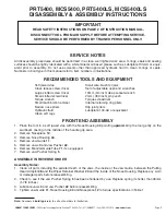
Page 2: ...ORE ATTEMPTING SERVICE SERVICE SHOULD ONLY BE PERFORMED BY TRAINED PERSONNEL WARNING SERVICE PROCEDURES SHOULD BE PERFORMED ONLY BY TRAINED SERVICE PERSONNEL INSTRUCTION MANUAL Page 2 EMHART TEKNOLOGIES 50 Shelton Technology Center Shelton CT 06484 Tel 877 EMHART1 Fax 800 225 5614 www emhart com ...

Page 3: ...exhaust towards anyone 10 Inspect the tool at regular intervals for damage and proper function Replace damaged parts immediately Do not connect a damaged tool to an air supply 11 Use only genuine Pop brand replacement parts EMHART TEKNOLOGIES 50 Shelton Technology Center Shelton CT 06484 Tel 877 EMHART1 Fax 800 225 5614 www emhart com Page 3 DESCRIPTION AND MODEL IDENTIFICATION The 5400 Series too...

Page 4: ...pen end rivets PRG540 127 Screw Use for Hydraulic oil replacement P342 Operator s Instructions P343 Instruction Manual PACKED IN CARTON MODELS PRT5400LS and MCS5400LS Part Number Part Name Data Model 5400 Rivet Tool Assembled with air line PRG540 56 Deflector Safety device PRT5400 LS only MCS5400 8 Collector bottle MCS5400 LS only PRT5500 6 Jaw Pusher 3 16 4 8mm and smaller dia rivets PRG540 46 Ja...

Page 5: ...am Assembly The Hydraulic Ram Assembly forces hydraulic fluid from the reservoir in the handle into the main hydraulic bore where it moves the hydraulic piston together with the attached pulling mechanism rearward As the pulling Jaws move rearward they close on and grip the rivet man drel and set the rivet When the trigger is released air at line pressure forces the hydraulic piston forward to the...

Page 6: ...or fatigue Attaching an air line coupler at the tool adds weight and changes the balance of the tool PRT5400 MCS5400 1 Select and attach the appropriate Nosepiece 12 A 12 B 12 C based on the rivet size mandrel diameter The PRT5400 and MCS5400 Models arrive assembled with Nosepiece 12 C suitable for 3 16 4 8mm diameter open end rivets To convert for smaller size rivets it is only necessary to chang...

Page 7: ...r or smaller rivets use the following parts Item 3 Jaws Part No PRG540 46 Item 22 Jaw Pusher Part No PRT5500 6 Item 71 Mandrel Guide Tube Part No PRG540 43 Item 12 Nosepiece PRN414 for 1 8 3 2mm diameter rivets PRN524 for 5 32 4 0mm diameter rivets PRN614 for 3 16 4 8mm diameter rivets For 1 4 6 4mm diameter rivets use the following parts Item 3 Jaws Part No PRG540 44 Item 22 Jaw Pusher Part No PR...

Page 8: ...lic Fluid Soft jawed vise 7 16 11mm open end wrench Procedure 1 Place the tool in a soft jaw vise making sure the Fill Screw 10 is point ing up 2 Remove the Nosepiece 12 the Fill Screw 10 and Seal Washer 4 3 Screw the Oil Replacement Screw into the Nose Housing where the Nosepiece 12 was removed Tighten only until resistance is felt 4 To properly add fluid the Hydraulic Piston 26 must be pushed ba...

Page 9: ...44 pointing upward Grip the tool gently on the aluminum casting in the middle of the handle grip area 2 Remove Nosepiece 12 3 Remove Nose Housing 44 4 Remove Jaw Guide 11 5 Remove Jaws 3 and Jaw Pusher 22 6 Remove Mandrel Guide Tube 71 if so equipped 7 Remove Jaw Pusher Spring 5 ASSEMBLE IN REVERSE ORDER Assembly Notes 1 Clean all parts including the serrated teeth of the Jaws the inside of the Ja...

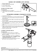
Page 10: ...d 38 Clamp Nuts 23 Right Clamp 42 and Left Clamp 43 4 Remove Intensifier Chamber 45 Intensifier Chamber Sleeve 46 and O ring 8 Pull out the Intensifier Chamber Sleeve 46 and remove Grommet 21 5 Slowly withdraw the Intensifier Assembly 29 by pulling up on the air piston 6 Remove the Ram Seal 40 from the Ram using a plastic or wooden wedge to push the seal off the end of the Ram Take care not to dam...

Page 11: ...ve Pulling Head Adaptor 28 and slide Seal Sleeve assembly 25 off the Hydraulic Piston Rod 8 To disassemble the Seal Sleeve 25 remove Seal Snap Ring 20 using internal retaining ring pliers Remove Seal Retainer Washer 19 Rod Seal 17 O ring 41 and Piston Rod Seal 6 Take care not to damage seal ing surfaces on the Seal Sleeve 9 Using narrow nose pliers squeeze and pull to remove Piston Seal 27 Note th...

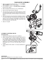
Page 12: ...ush the Ram Sleeve 6 Remove the Restrictor 2 and Restrictor Seat 33 from the end of the Ram Sleeve 32 If the Restrictor and Restrictor Seat remain in the tool they can be dislodged by blowing com pressed air into the Fill Screw hole while covering the other end of the casting to catch the parts 7 Remove O ring 36 ASSEMBLE IN REVERSE ORDER Assembly Notes 1 Lubricate all O rings and seals prior to i...

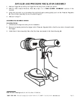
Page 13: ... 16 and the Valve Plug 15 4 Remove O rings 7 ASSEMBLE IN REVERSE ORDER Assembly Notes 1 Lubricate all O rings and seals prior to installation 2 Be sure to properly position the trigger slot in Pressure Regulator 39 so that the low side is forward toward the trigger 3 Install the Air Valve Assembly 16 so that the holes are parallel to the Nose Housing 44 EMHART TEKNOLOGIES 50 Shelton Technology Cen...

Page 14: ...move Pump Retainer 52 4 Remove Vacuum Pump Assembly 53 consisting of two brass turnings 5 Remove two O rings 70 ASSEMBLE IN REVERSE ORDER Assembly Notes 1 Lubricate all O rings and seals prior to installation 2 Take care not to wrinkle or cut O rings during assembly VALVE HOUSING SUB ASSEMBLY 1 Remove O rings 8 and 35 2 Remove Valve Body Ring 69 3 To remove the Valve Body 60 from the Valve Housing...

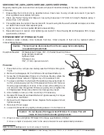
Page 15: ... will free up the seals IMPORTANT TOOL MUST BE DISCONNECTED FROM THE AIR SUPPLY All procedures must be performed in a clean environment Use only approved hydraulic fluids specified in this manual Use hydraulic fluid that is clean and free from air bubbles Take care to prevent foreign matter from entering the tool CAUTION Disconnect the tool from the air supply before proceeding EMHART TEKNOLOGIES ...

Page 16: ...n of the hydraulic fluid 10 Position Ram Assembly 29 over Ram Sleeve 32 and tilt slightly to immerse one edge of Ram Seal 40 into the fluid then straighten to fully immerse the seal without entrapping air Push the Ram Assembly in as far as it will go The Hydraulic Piston Rod 28 will move rearward 11 Remove Ram Assembly 29 and repeat steps 8 9 and 10 above 12 Remove the tool from the vise and stand...

Page 17: ...e all seals and O rings Inspect all parts for wear or damage and replace as needed 2 Lightly lubricate all seals O rings and front end parts before reassembling Table 1 TORQUE SPECIFICATIONS Torque in Torque in Torque in Item Description Newton Meters Inch Pounds Foot Pounds 12 Nosepiece 6 8 7 3 60 65 5 0 5 4 44 Nose Housing 52 0 54 2 460 480 38 3 40 0 11 Jaw Guide 20 3 24 9 180 220 15 0 18 3 28 P...

Page 18: ...ING 1 42 PRT5400 42 RIGHT CLAMP 1 43 PRT5400 43 LEFT CLAMP 1 44 A PRT5400 22 NOSE HOUSING PRT MCS5400 1 44 B PRT5400 72 NOSE HOUSING PRT MCS5400LS 1 45 A PRT5400 29 INTENSIFIER CHAMBER PRT MCS5400 1 45 B PRT5400 79 INTENSIFIER CHAMBER PRT MCS5400LS 1 46 A PRT5400 30 INTENSIFIER CHAMBER SLEEVE PRT MCS5400 1 46 B PRT5400 70 INTENSIFIER CHAMBER SLEEVE PRT MCS5400LS 1 71 PRG540 43 MANDREL GUIDE Instal...

Page 19: ... 33 2 36 32 39 16 7 15 37 43 38 34 9 1 13 14 8 31 6 25 41 17 19 20 10 4 18 28 5 22 A 24 27 M AD E IN U S A 35 8 49 48 47 47 52 53 68 67 69 8 12 B 44 11 3 A 71 3 B 12 A 12 C 12 D 22 B 72 EMHART TEKNOLOGIES 50 Shelton Technology Center Shelton CT 06484 Tel 877 EMHART1 Fax 800 225 5614 www emhart com Page 19 ...

Page 20: ...es Coquelicots 94385 Bonneuil sur Marne Cedex France Tel 33 1 56 71 24 24 Fax 33 1 56 71 24 34 Norway Postboks 153 Leirdal 1009 Oslo Norway Tel 47 22909990 Fax 47 22909980 Spain Carretera M 300 Km 29 700 28802 Alcalá de Henares Madrid Spain Tel 34 91 887 1470 Fax 34 91 881 7278 Sweden Skjutbanev 6 Box 203 SE 70144 Örebro Sweden Tel 46 19 2058000 Fax 46 19 260038 United Kingdom 177 Walsall Road Bir...

Reviews: