60
6.1.3.
Front anti-roll bar
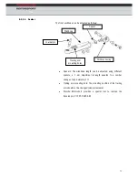
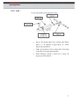
The front anti-roll bar has a 7 position adjustment range on both sides,
each position results in the blade being adjusted by an angle of 15°. The
maximum stiffness of the anti-roll bar is achieved when the blade is
aligned parallel to the anti-roll bar link. The minimum stiffness is achieved
when the blade is aligned at 90° (Pos1-1) to the anti-roll bar link.
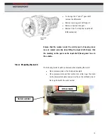
Always use suitable tools to rotate the blade as incorrect tools can cause
damage. Notches or other damage can cause the blade to break.
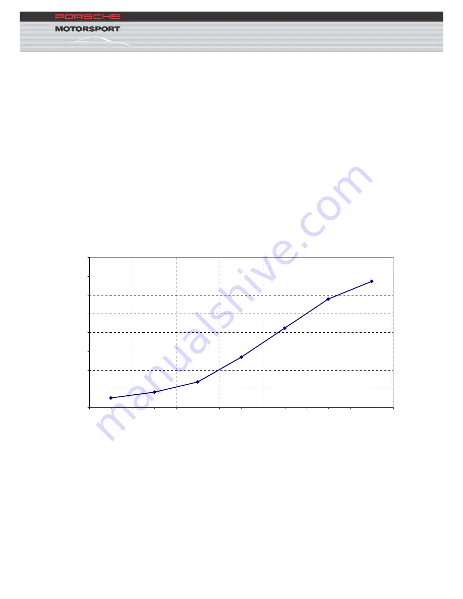
In the following diagram the component stiffness of the front ARB
dependent on blade position is represented:
Front ARB
30
35
40
45
50
55
60
65
70
Po
s 1
-1
Po
s 2
-2
Po
s 3
-3
Po
s 4
-4
Po
s 5
-5
Po
s 6
-6
Po
s 7
-7
St
iffn
es
s
[N
/mm]
Summary of Contents for 911 GT3R 2010
Page 1: ...Technical Manual Model 2010...
Page 10: ...7 3 3 Engine power and torque curves...
Page 44: ...41 4 3 Exhaust system 4 3 1 Standard system 4 3 2 Catalytic converter 100 cells...
Page 45: ...42...
Page 79: ...76 rm 6 3 2 4 Trailing a 8 mm Buchse 28 mm Buchse...
Page 107: ...104 r 9 2 1 Front bumper 9 2 Exterio...
Page 108: ...105 9 3 Rear wing P1 P12 Left wing support Gurney 10mm...
Page 139: ...136 10 12 Relay and fuse ass 10 12 1 Fuse holder ignment...
Page 141: ...138 10 12 4 MS4 sensor system...

