background image


63 

6.2.


Rear suspension 


Multi-link suspension 


Adjustable main spring 


Adjustable anti-roll bar 


Two way adjustable dampers 

6.2.1.


Rear springs 

The rear coil spring has a four-step adjustment range, the corresponding 
spring rates are listed in the table below:  

Colour 

Part number 

Stiffness Range [N/mm] 

light green  997.333.531.9B

170 - 230 

green 

997.333.531.9A

220 - 280 

braun 

997.333.531.9C

250 - 320 

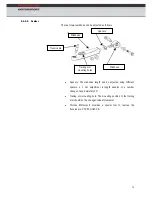
The spring is twisted into or out of the spring saddle in the individual 
positions to achieve each spring rate. The maximum spring stiffness is 
achieved by screwing the spring completely into the spring saddle. 


Changing the spring rate (spring st


iffness) directly affects the vehicle ride 

eight as well as the toe. The ride height must be adjusted by four 

volutions to compensate for one step in spring rate change. For 

xample, when the spring rate is softened by one step the ride height 

ust be lowered four turns to compensate. If the spring rate is stiffened 
e  ride  height  must  be  raised  by  four  turns.  Changing  the  ride  height 

bout 10 mm changes the toe about 5.7`. The ratio of the front spring is 

.73. The thread pitch of the spring saddle is 1.5. 

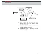
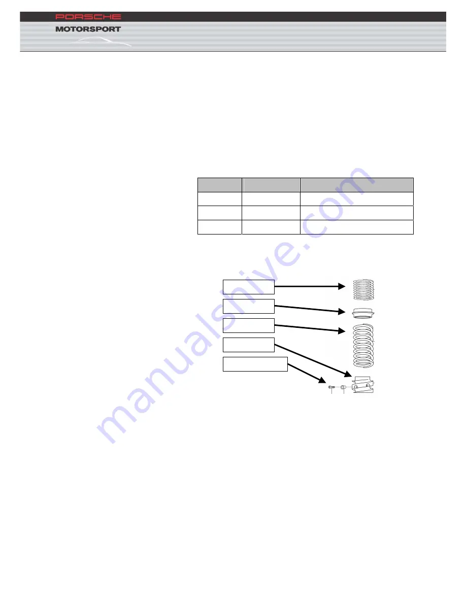
Helper spring

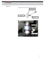
Spacer ring

Main spring

Spring 

Locking screw

h
re
e
m
th
a
0
 

Summary of Contents for 911 GT3R 2010

Page 1: ...Technical Manual Model 2010...

Page 2: ...e possibility to reference data adjustment values and working procedures and make the maintenance and repair work on the vehicle easier We wish you every success with your GT3 R Dr Ing h c F Porsche A...

Page 3: ...accepts no guarantee that the vehicle conforms to the regulations The car can not be registered for road use and does not comply with German road traffic regulations Illustrations descriptions and sc...

Page 4: ...ling system 12 3 6 Induction system 19 3 7 Throttle butterfly 20 3 8 Working on the engine 22 3 9 Engine component tightening torques 35 3 10 Engine mileage 36 4 FUEL AND EXHAUST SYSTEM 37 4 1 Fuel sy...

Page 5: ...91 7 WHEELS 93 7 1 Wheel nuts 93 8 BRAKE SYSTEM 95 8 1 Technical data brake system 95 8 2 Brake force distribution brake balance 95 8 3 Brake caliper 102 8 4 Tightening torques brake system 102 9 CHAS...

Page 6: ...10 ABS 125 10 11 Traction control 131 10 12 Relay and fuse assignment 136 11 CAR MAINTENANCE 139 11 1 After approx 200 km and or first test 139 11 2 After every session 139 11 3 After every race week...

Page 7: ...iner Sauter 0711 911 84994 0170 911 3436 Fax 0711 911 89535 Sport parts sales Mr Friedrich Weseler 0711 911 89854 Mr Karlheinz Kienle 0711 911 82923 Mr Klaus Lenzner 0711 911 82423 Mr Christian M ller...

Page 8: ...of gears sequential 6 2 1 Dimensions Length w o spoiler edge mm see homologation papers Width across front axle mm see homologation papers Width across rear axle mm see homologation papers Wheelbase...

Page 9: ...ssion ratio approx 14 5 Maximum revs rpm 9 400 Inlet valve diameter mm 41 Inlet valve lift mm 14 Point of maximum inlet valve lift after TDC Exhaust valve diameter mm 35 5 Exhaust valve lift mm 13 5 P...

Page 10: ...7 3 3 Engine power and torque curves...

Page 11: ...n The 911 GT3 R is equipped with a dry sump lubrication system The oil tank is mounted to the engine The engine oil is cooled by an oil water heat exchanger mounted on the engine 3 4 1 Engine oil Mobi...

Page 12: ...Piston cooling 2 Pressure pump 10 Timing chain tensioner 3 Safety valve 11 Camshaft 4 Oil filter 12 Camshaft housing scavenge pump 5 Pressure sensor 13 Crankcase scavenge pump 6 Oil water heat exchang...

Page 13: ...oil tank through the dip stick guide sleeve Therefore the oil level should only be measured again after waiting for a few minutes The engine oil level must be checked regularly and corrected when nece...

Page 14: ...ay An optional oil level display is available 997 641 139 9A The car wiring loom is already prepared for use of this display The connector for the display is located in the area of the rear side windo...

Page 15: ...12 3 5 Engine cooling system The GT3 R cooling system is a standard cooling system optimised for use in a race car 3 5 1 Scheme drawing...

Page 16: ...ditions see parts catalog When competing under warmer conditions the car should be driven without the thermostat in order to reduce the temperature level of the cooling system with thermostat supply r...

Page 17: ...ine coolant is replaced by 24 3 litres of water and 2 litres of anti corrosion additive part number 997 106 907 90 which protects the water galleries and other cooling system parts from corrosion redu...

Page 18: ...ter an engine change for example Attention When the water system has reached its operating temperature the expansion tank cap should under no circumstances be opened and the pressure released Since th...

Page 19: ...r improves the initial reaction from the heating system the valve remains open in the race car system allowing the system to be bled continuously A special filling system available from Sobek should b...

Page 20: ...of the filling system Pressure Scavenge Switch on the pump The system will be filled The device must run for ten minutes to guarantee that the system is correctly filled and bled Warm up the engine 80...

Page 21: ...rvoir with a coupling The reservoir is charged with a pressure of 2 5 3 0 bars The system filling procedure should be carried out as follows Disconnect the quick release fitting in the engine bay and...

Page 22: ...19 3 6 Induction system Vacuum actuator Reso 2 su2 2 stage resonance induction system Activated by vacuum actuator resonance valve 3 6 1 Under pressure routing...

Page 23: ...20 3 7 Throttle butterfly Electronically actuated single throttle butterfly Redundant system two potis For information on the EGAS system refer to 10 9...

Page 24: ...butterfly and the throttle pedal The signal of the pedal is transferred to the throttle butterfly via an electro motor An adjustment of the throttle butterfly is not necessary After turning on igniti...

Page 25: ...nd fit the bolt strain gauge Tighten to the required elongation 0 160 0 005 mm With a torque wrench check to see if a minimum torque of 55 90 Nm was achieved Loosen the second bolt and follow the abov...

Page 26: ...bolts to 20 Nm before finally tightening to 120 torque angle 3 8 3 Set valve timing 3 8 3 1 Special tools Porsche Motorsport recommends use of the following special tools to adjust and set the valve t...

Page 27: ...er and lower valve spring seats till coil bound with a spring balance before reducing the stack height slightly 0 7 1 0 mm 2 Record the spring stack height seat to upper edge of spring seat 3 Add the...

Page 28: ...aining key pulley 000 721 973 21 Press tool crankshaft seal 000 721 216 40 Spacer for press tool 000 721 979 71 Protective cap crankshaft 000 721 979 70 3 8 6 2 Removal 1 Remove the pulley from the cr...

Page 29: ...ed end of a commercially available slide hammer 1 into the drilled holes Carefully remove the seal 2 by swapping the slide hammer alternatively between the drilled holes 6 Make a drill jig according t...

Page 30: ...pointed end of a commercially available slide hammer alternatively into the two holes and pull out the seal 11 Remove swarf 12 Thoroughly clean the flange with a cleaning solvent or acetone 3 8 6 3 In...

Page 31: ...to the crankshaft flange and fit the hexagon head bolt 3 17 mm AF 6 Tighten the hexagon head nut 4 till the spacer 2 touches the crankshaft flange 7 Leave the tool fitted for approximately two minutes...

Page 32: ...fit the flywheel side crankshaft seal Pressure pad 000 721 912 60 Seal extractor jig 000 721 971 90 3 8 7 2 Removal 1 Drill two holes 2 5 mm 180 opposed from one another into the metal ring of the cra...

Page 33: ...fitted behind the crankshaft seal which should prevent the possibility of the seal being fitted inclined Aluminium swarf which may appear during drilling should be carefully removed 7 Remove the seal...

Page 34: ...y circumstances be treated with emery cloth polish compounds or wire brushes Remove corrosion on the crankshaft flange with a special metal polish wad Afterwards carefully clean the crankshaft flange...

Page 35: ...push it onto the base plate 3 Fit the seal dry 4 Remove the magnetic cone and using the pressure piece 000 721 912 60 push the crankshaft seal in a coplanar position 5 Fasten the insertion jig mountin...

Page 36: ...ly tools for one or two minutes in the final position the seal and sealing lip position themselves as a result 9 Loosen the inserting nut and remove the hexagon head bolt of the inserting jig remove t...

Page 37: ...34 Measurement depth is approximately 5 mm Maximum permissible misalignment is 0 5 mm 11 If the comparable values exceed the maximum difference use the insertion jig again to press home...

Page 38: ...t crankcase M20 x 1 5 70 Water drain bolt cylinders M10 x 1 10 Flywheel M10 90 Cylinder head Cylinder head bolt M10 see 3 8 2 Camshaft housing Anti knock sensor M8 23 Spark plugs M12 x 1 25 20 Spark p...

Page 39: ...36 3 10 Engine mileage The engine in the 2010 911 GT3 R is designed to rev to a maximum of 9 400 rpm in this case the rebuild interval is 30 hours...

Page 40: ...system Main pump Fuel filter Engine supply Pressure regulator Reserve pump No return fuel system FT3 safety fuel cell Fuel cell volume 100 l Integrated 10 l catch tank double tank 6 5 3 5 l 4 intank...

Page 41: ...the main and reserve fuel pumps are of the electrical vane type The fuel filter is located in the front luggage compartment and should be replaced after approximately every 24 hours of use A scavenge...

Page 42: ...aks in the system can cause leakage and in the worst case the system pressure can exceed the burst pressure of the fuel filter 4 2 1 Pressure regulator The 911 GT3 R is equipped with a returnless fuel...

Page 43: ...andard and is activated from a switch mounted on the dashboard A warning lamp in the push button is illuminated when the reserve pump is running 4 2 4 Main and in tank pumps A switch mounted on the da...

Page 44: ...41 4 3 Exhaust system 4 3 1 Standard system 4 3 2 Catalytic converter 100 cells...

Page 45: ...42...

Page 46: ...arbox technical data Gearbox type G 97 71 Design Sequential Number of gears 6 Standard gear ratios Drop Gear 25 32 1 280 Crown wheel pinion 9 26 2 889 1st gear 13 41 3 154 2nd gear 17 39 2 294 3rd gea...

Page 47: ...44 5 2 Gear ratio diagram 0 1000 2000 3000 4000 5000 6000 7000 8000 9000 0 50 100 150 200 250 300 v km h n 1 min...

Page 48: ...tion when shifting gear 5 3 1 Gearbox potentiometer calibration The gear position sensor must be recalibrated after repairs are carried out on the gearbox or if the gear ratios are changed Turn on the...

Page 49: ...namic locking value The differential is checked by means of a friction test in which the preload and wear of the clutch disc plates are determined 5 4 1 Differential assembly 6 Clutch disc 4 per side...

Page 50: ...gearbox works perfectly 5 6 1 Special tools 997 450 116 9A Assembling tool clutch Wire bow for preload while assembling deliverable 997 450 372 9A Assembling tool Tool fitting release spearing deliver...

Page 51: ...Add Mobilube SHC through the oil fill opening till the oil overflows from the above mentioned tube approx 3 litres for a newly build gearbox Close the oil overflow pipe and add 1 0 litre of oil Porsc...

Page 52: ...from the M32 x 1 25 nut Remove anti rotational safety Loosen M32 x 1 25 nut Completely remove gear ratio housing Extract shift rod Remove shift forks Remove circlip from input shaft Remove M 32x1 25 n...

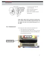
Page 53: ...is seated correctly when fitting the input shaft Ensure that the marking on the gears on the input shaft fixed gears face to the outside 5 6 4 Mounting the clutch The following points should be obser...

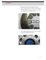
Page 54: ...S Flywheel Side mark on the drive plates must point towards the engine Furthermore the FS mark of each drive plate should lie on top of each other FS mark FS Mark After the third intermediate plate th...

Page 55: ...52 Then insert drive plate 3 and intermediate plate 4 Attention The clutch plates should be refitted in the original sequence and orientation Please observe the markings on the edges...

Page 56: ...htly with copper grease Porsche part number 000 043 004 00 before assembly 5 6 5 Release bearing Under no circumstances whatsoever must gearbox come into contact with the clutch release bearing seal o...

Page 57: ...hub and gear roller bearings for signs of wear and pitting Check the oil for signs of metallic debris The following work should be carried out after a total running time of approximately 30 hours Che...

Page 58: ...55 5 6 7 Starter motor maintenance The starter motor maintenance includes the following work After each race Shell Stamina Grease HDS ET Nr 997 605 920 9A 400 g...

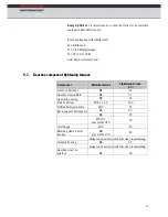
Page 59: ...t dimensions Tightening torque Nm Clutch on Flywheel M8 33 Gearbox closure plate M6 9 7 Gear ratio housing M8 25 Pinion shaft nut M32 x 1 25 180 Differential closure plate M10 55 Reverse gear shaft su...

Page 60: ...in spring Adjustable anti roll bar Two way adjustable dampers 6 1 1 Front springs The front coil spring has a three step adjustment range the corresponding spring rates are listed in the table below C...

Page 61: ...and rebound compression droop is fitted to the front axle The bump and rebound damping forces are adjustable in the high speed piston range Both softer and harder are adjusted on the valve block 6 1...

Page 62: ...curves F2T1 1 2 4 6 8 10 16 1 2 4 6 8 10 16 12 14 12 14 5000 4500 4000 3500 3000 2500 2000 1500 1000 500 0 500 1000 1500 2000 2500 3000 3500 4000 0 0 131 0 262 0 393 0 524 piston speed m s bump dampin...

Page 63: ...ti roll bar link The minimum stiffness is achieved when the blade is aligned at 90 Pos1 1 to the anti roll bar link Always use suitable tools to rotate the blade as incorrect tools can cause damage No...

Page 64: ...eakage When implementing the test this level of system pressure should be held for an absolute maximum of ten seconds If it is necessary to repeat this procedure a pause of at least 10 seconds should...

Page 65: ...he engine is running Fill the reservoir before starting the engine to bleed the system Recheck the reservoir level immediately after the engine has started Rotate the steering wheel quickly and repeat...

Page 66: ...maximum spring stiffness is achieved by screwing the spring completely into the spring saddle Changing the spring rate spring stiffness directly affects the vehicle ride eight as well as the toe The...

Page 67: ...mp The bump is adjustable in the high speed range The high speed adjustment range has 16 positions 1 less damping forces 16 higher damping forces Attention When changing the existing dampers for those...

Page 68: ...2 4 6 8 1 2 4 6 8 14 16 10 10 12 6500 6000 5500 5000 4500 4000 3500 3000 2500 2000 1500 1000 500 0 500 1000 1500 2500 3000 3500 4500 5000 5500 0 0 131 0 262 0 393 0 524 piston speed m s bump damping f...

Page 69: ...mum stiffness is achieved when the blade is aligned at 90 Pos 1 1 to the anti roll bar link Always use suitable tools to rotate the blade as incorrect tools can cause damage Notches or other damage ca...

Page 70: ...or electronic or mechanical suspension alignment device The measurement procedure described in the device operating instructions should be followed Electronic suspension alignment devices can be purch...

Page 71: ...following points must be followed before alignment can begin Set the front and rear tyr set up wheels are used their dimensions must correspond with the tyre dimensions at the r Measure the wheel alig...

Page 72: ...o check the t and rea d be loaded and unloaded ompressed several times to allow the suspension to settle The ride height is adjusted by rotating the lower spring platform The car must be p level surfa...

Page 73: ...screw Porsche Motorsport provides a special tool to remove the trunnion pin 997 450 349 9B 6 3 1 2 Toe Clamp screw 2 mm spacer 2x 4 mm spacer The steering gear is shimmed on the two mounting points b...

Page 74: ...ximately 13 Trailing arm mounting hole The mounting position of the trailing t be changed wheel clearance Porsche Motorsport provides a special tool to remove the 450 345 9B 6 3 1 3 Camb The front wis...

Page 75: ...72 rm 6 3 1 4 Trailing a 6 3 1 5 Upper mount The upper mount position can be adjusted by using the slots in the car body 28 mm Buchse 8 mm Buchse...

Page 76: ...urface set up platform to check the ride height The front and rear suspension should be loaded and unloaded compressed several times to allow the suspension to settle Ride height adjustment is made by...

Page 77: ...74 The length of the toe rod can be adjusted using the clamp bolt 6 3 2 2 Toe Bearing journal Spacers Clamp bolt 2x 4 mm Scheibe 2 mm Scheibe...

Page 78: ...ing arm mounting hole The mounting position of the trailing arm should not be changed wheel clearance Porsche Motorsport provides a special tool to remove the trunnion pin 997 450 345 9B 6 3 2 3 Camb...

Page 79: ...76 rm 6 3 2 4 Trailing a 8 mm Buchse 28 mm Buchse...

Page 80: ...1 543 90 1 996 341 543 90 0 8 996 341 543 98 0 8 996 341 543 98 0 6 996 341 543 97 0 6 996 341 543 97 spacer shims mm 0 3 996 341 543 96 0 3 996 341 543 96 trunnion pin mm 76 997 341 413 9H 80 997 341...

Page 81: ...bound 6 10 Anti roll bar 2 2 4 4 1 soft 7 stiff Length trailing arm 362 mm 372 mm Length upper wishbone front 261 mm rear 255 mm Due to transportation purposes the delivery setup of the car does not m...

Page 82: ...ng seat in ter being pu Tight the wheel bearing er to the stipula A of one w g change per upright bearing seat reco by Motorsport Re tighten eel bearing cover to the stipu fter approximatel 200 km 6 4...

Page 83: ...ightening Torque Position Dimension Nm 2 M14 x 1 5 x50 160 3 M12 x 1 5 x30 100 5 M12 x 1 5 100 10 M10 x 1 5 65 20 M8 25 22 M8 45 with Loctite 243 23 M12 x 1 5 75 replace after dismounting 29 M14 x 1 5...

Page 84: ...nt side 4 5 M6 x 16 8 8 10 10 M8 x 35 10 9 37 11 Grease b with l hu ongtime grease 13 31 w ctite 270 M8 ith Lo 14 470 retig ten after 100 km eassembled per paste on contact surface h when r Cop 15 500...

Page 85: ...82 nt 6 5 3 Anti roll bar fro Tightening Torque Position Dimension Nm 2 M6 10 11 M10 50 12 M8 LH 23 14 M8 23 16 M6 10...

Page 86: ...83 nt 6 5 4 Suspension stut fro Tighteni orque ng T Position Dimension Nm 9 M6 x 12 10 12 M8 75 13 M14 40 16 M8 35...

Page 87: ...Steering gear Tightening Torque Position Dimension Nm 2 M10 x 45 10 9 70 8 M18 x15 90 track rod on steering gear 9 M14 x 1 5 50 11 M6 x 20 10 15 M14 x 1 5 75 16 12 x 1 5 75 replace r dismounting M 10...

Page 88: ...85 n 6 5 6 Steering colum Position Dimens Tightening Torque ion Nm 3 0 9 3 M8 x 35 1 7 5 0 M1 46 11 M5 8 15 35 M5 x 5 18 1 5 50 5 M16 x...

Page 89: ...86 6 5 7 Side part rear Tightening Torque Position Dimension Nm 2 M12 x 97 75 with Loctite 270 3 M12 x 1 5 10 9 110 5 M12 x 80 110 6 M12 x 1 5 110...

Page 90: ...Nm 6 M12 100 7 M8 25 12 M5 8 14 M8 45 with Loctite 243 15 M12 x 1 5 75 replace after dismounting 17 M14 x 1 5 160 23 M14 x 1 5 160 25 M12 75 32 M12x1 5 110 33 M12 x 70 110 34 M12 x 1 5 110 37 M6 x 20...

Page 91: ...Nm 4 M8 x 35 37 7 tite 270 M8 31 with Loc 5 Grease hu e b with longtime greas 8 470 retighten after 100 km when reassembled Copper paste on contact surface 9 500 25 16 M6 x 16 10 17 M6 x 12 10 27 M6...

Page 92: ...89 ear 6 5 10 Anti roll bar r Position Dimension Tightening Torque Nm 2 M6 10 9 M4 x 10 2 12 M8 LH 25 14 M12 46 15 M6 10 20 M8 25 22 M8 x 25 25 23 M6 x 12 10...

Page 93: ...90 ear 6 5 11 Suspension strut r Tighteni orque ng T Position Dimension Nm 3 upper M12 x 1 35 3 lower M12 x 1 40 15 M10 46...

Page 94: ...Rudolf Diesel Stra e 11 13 53520 Meuspath Phone 49 2691 9338 54 Fax 49 2691 9338 50 Service partner for the UK BG Motorsports Ltd 47 48 Silverstone Circuit Silverstone Northants NN12 8TN Phone 44 132...

Page 95: ...hould be overhauled Oceanshore Mo D 5892 John Anderson Highway 32136 Flagler Beach FL Phone 1 386 67319 Fax 1 386 673 Service partner for Asia E 1 36 Ootsuzaki Ogakie cho Kariya shi Aichi ken 448 081...

Page 96: ...ts The aluminium wheel nuts are marked as follows Right hand side of car left hand thread colour blue Left hand side of car right hand thread colour red Porsche recommends that the wheel nuts are also...

Page 97: ...essary for both vehicle sides Source of ino Paoli S r l www dinopaoli com E Mail info dinopaoli com he smooth operation of the wheel safety mechanism integrated in the shown that the centre lock threa...

Page 98: ...k thickness mm 32 32 Brake pad Pagid RS 19 gelb Pagid RS 19 gelb Pad thickness mm 22 22 Brake caliper 6 piston 4 piston Brake caliper pisto meter mm n dia 38 30 28 35 28 Brake fluid Endless RF 650 Rac...

Page 99: ...96 system 8 2 1 Brake balance If the brake balance potentiometer is rotated the lever ratio dimension x on the balance bar is adjusted directly by a adjuster cable Balance bar rod acer Balance bar Sp...

Page 100: ...orce HA Brake force VA l rear brakeforce pedalforce front brakeforce l x pedalforce rear brakeforce _ _ _ 8 2 1 1 Basic setting balance bar llowing dimensions must be set in the basic setting 0 The fo...

Page 101: ...fficient axial play o a p is syst is play balance bar ystem is mounted on the car Therefore the play has to be re checked hen the balance bar system is mounted on the car The pitch of the threaded bal...

Page 102: ...that with the maximum positive rotation in the anti clockwise the er cable lock nut clevis to pr 2 mm Under all circumstances avoid the system being fitted with preload The pushrods of the two master...

Page 103: ...to 0 with the MoTeC system before 8 2 1 3 Brake balance system maintenance The brake balance system is comprised of many moving parts In general all joints should be free of friction and no parts sho...

Page 104: ...irclip 1 2 Carefully remove the internal components 3 Remove dirt deposit in the cylinder 4 Coat the cylinder with brake fluid 5 Replace the following parts when rebuilding the master cylinder Main se...

Page 105: ...pers which includes new pistons and seals There are two bleed nipples on each brake caliper If a pressure manometer is connected to the caliper it should be noted that the system including manometer i...

Page 106: ...ct e weight Interior ring wheel Race bucket seat with fire resistant upholstery fabric only driver 9 Chassis DO NOT under any circumstances modify the roll cage as its struct b Porsche Motorsport All...

Page 107: ...104 r 9 2 1 Front bumper 9 2 Exterio...

Page 108: ...105 9 3 Rear wing P1 P12 Left wing support Gurney 10mm...

Page 109: ...ed from frost remove from vehicle The operating pressure of system is 14 bars and should be checked regularly using the manometer mounted to the extinguisher bottle The extinguishing agent extinguishe...

Page 110: ...ng lamp will glow Return the switch to the original position Press the dashboard mounted push button If the switch is functioning correctly the trigger box warning lamp will glow Trigger box connectio...

Page 111: ...ns an over pressure valve eral oil based cleaning agents en when jacks are retracted grooved nut air jack fixed mount must be checked during the standard maintenance procedure nut rear 45 5 Nm re belo...

Page 112: ...1 Car lift system Never u ird party product as this can lead to damage to the air jack over or piston tube be changed immediately Please refer to the manufacturer s product description Krontec for fur...

Page 113: ...h 10 3 Steering wheel ce steering wheel parts of the release coupling are balanced together and therefore have to be used in only one combination numbers on steering wheel and hub must match TAG 140 A...

Page 114: ...dlight flash if the button is pressed for about 1 second the headlights stay on till the next time the button is presse WIPER Wiper DISPLAY Change MoTeC display pages ALARM Reset MoTeC Alarm MAP Chang...

Page 115: ...Fire extuingisher Head light FIRE LIGHT EEN runs when engine runs nly to ABS ABS on off WINDSCR Pulled 100 windscreen Pushed floor air vents driver ventilation FUEL PUMPS Fuel pump Bosch Pump Middle p...

Page 116: ...ontrol mode MOTEC MODE Switch through the different MoTeC display setups practice warmup race HAZARD Hazard lights FOG REAR Fog lights 10 5 Shift Light Module The Shift Light Module SLM is located abo...

Page 117: ...1 Display modes The MoTeC Dash has three different display modes Race Warm up Practice The information displayed differs between each mode The MoTeC Mode switch in the centre console is used to page...

Page 118: ...balance Top Traction control setting ight Actual lap time Previous lap time Engine temperature ET Oil temperature OT Oil pressure OP Fuel consumption per lap FL Battery voltage on dash VOLTS mounted D...

Page 119: ...ging LOG_RUN 10 6 1 3 Warm up mode entre Gear ight ottom OT Gearbox oil temp GT Data logging LO Throttle valve angle THR_POS Accelerator pedal angle PEDAL Brake bias BRBIAS Front brake pressure BF Rea...

Page 120: ...17 G Vert G ODO le SW_ANG r GEARS Vertical acceleration Lateral acceleration G Longitudinal acceleration Odometer Trip distance TRIP_D Steering angle STANG_W Steering wheel ang Gearbox potentiomete EN...

Page 121: ...tion with this version Delivered with the car is a CD with the p figuratio Under NO circumstances should the USB connection cable PC MoTeC Dash be removed or the power supply cut during the up or down...

Page 122: ...es pcrank_rel 300 mbar Camshaft sensor camshpos 20 30 KW Speedsensor crankshaft RPM nmot_w Water level switch Water Level Gearbox Gear lever sensor Gear Lever Force Volt 2 ugs_w 2 5 V Gearbox poti Gea...

Page 123: ...hased from Porsche to dele rrors 10 8 S With the MODAS software various parameters can retrieved from the ECU In ad ved in an error log that can be retriev is T ust have the following minim ents 2000...

Page 124: ...module must only be implemented after tion with Bosch Engineering GmbH and must be approved by the r must have two hunt circuits To ensure that a defect does not rcuit the sensor earth sensor power s...

Page 125: ...ave an emergency stop switch which when actuated must a Is such The wiring loom between the primary power supply emergency stop switch pedal value logging control unit optional ETC amplifier and throt...

Page 126: ...rom EGas systems known from high volume production Therefore the system diagnostics should be run every time before the car is used The EGas diagnosis mode of operation and the error responses are des...

Page 127: ...ot necessary for the driver to apply the throttle blip when downshifting 10 9 14 Operating principle There is no mechanical connection between the accelerator pedal the the throttle valve The pedal as...

Page 128: ...10 10 ABS The ABS function is realised as a compromise between driveability and break performance Driveability is of big importance on a street car The ABS is supposed to allow the c For motorsport pu...

Page 129: ...S becomes active The brake pressure at each wheel is corrected until the wheel slip is back in the optimum range to be able to brake at the highest deceleration rate The comparison of the measured and...

Page 130: ...d for the actual Michelin tires This circumference is 2 2230 mm on the rear If different tires are used o circumference for the ABS system when tires from a circumference the following step Open the M...

Page 131: ...ic control unit 1 Hydraulic control unit with integrated ECU Front left brake line Rear right brake line 7 Front right brake line 8 Rear left brake line 2 Connecting cable 3 Rear brake circuit 4 Front...

Page 132: ...y and the outer LEDs start to flash By pushing the alarm button on the steering wheel the alarm disappears The alarm gets active again 45 seconds after the alarm button has been pushed 10 10 6 Diagnos...

Page 133: ...o Mark 00_clear_error_s left display side Click on Conn 2 write Rightclick on 00_clear_error_s execute Check the error memory one more time to ensure that the previous detected errors are not present...

Page 134: ...ng wheel the setting of the traction control can e changed 12 different settings are available 1 less traction control ction control entre console Under wet the conditions the switch should be flipped...

Page 135: ...s target slip during cornering and more intensive torque reductions Use FSLSGG to make a general setup of the handling correction 10 11 1 1 Target slip FSLSV is the base factor for the calculation of...

Page 136: ...to instability and system oscillations ller 10 11 1 4 PID controle FPASR is the amplification factor of the P component of the TC controller The P component proportional component of the controller c...

Page 137: ...er and strong oscillations in the drivetrain Calibration of a PID controller needs a lot expertise in control engineering 10 11 1 5 Driver influenc KLMIFAASR dry condition and KLMIFAASR_WET wet condit...

Page 138: ...ct rad_fl vrad_fr vrad_rl vrad_rr on the same level on the straight If you are not sure about your calibration go back to the neutral values Watch the recorded data and compare to this manual to find...

Page 139: ...136 10 12 Relay and fuse ass 10 12 1 Fuse holder ignment...

Page 140: ...in the front trunk on the left side The fuse has to be secured by a tie wrap 10 12 3 Power steering pump The fuse for the power steering pump is situated in the front trunk on the right side The fuse...

Page 141: ...138 10 12 4 MS4 sensor system...

Page 142: ...tion of all sy tems hoses and cables etc for leakage damage or chafing Check the specified torque setting of every safety relevant fastener Check dampers for leakage Drain the fuel and calculate the f...

Page 143: ...leakage and seated correctly Check seat and safety harness Check fire extinguisher 11 4 After 3 4 race weekends sprint e calipers r 11 5 After 30 hours running time 11 3 After every race wee Engine oi...

Page 144: ...orsche AG Imprint Publisher Dr Ing h c F Porsche AG Sales and Marketing Special and Motorsport Cars Porschestra e 71287 Weissach Postfach 1140 71283 Weissach Editorial Steffen H llwarth 01 2010 Illust...

Reviews: