background image

6

CONNECTED TO THE TRUCK
BEING SERVICED. DAMAGE TO
THE HYDRAULIC SYSTEM
COULD ACCURE IF NOT
PROPERLY CONNECTED
BEFORE ACTIVATING THE
HYDRAULIC SYSTEM.

Make sure the clutch engagement lever
is in the “out” position

Make sure all hoses are connected for
correct flow direction to and from the
truck being serviced. When routing hose
in the work area, position them where
personnel will not be at risk of tripping
over them or where vehicles can run
over the hoses. Do not lay hose over
sharp projects.

WARNING: PRESSURIZED FLUID
ESCAPING FROM A DAMAGED
HOSE CAN PENETRATE THE
SKIN AND BE INJECTED IN THE
BODY CAUSING INJURY OR
DEATH.

2.6 Work Area Safety Precautions

- Never operate the power unit in a

closed space. Inhalation of
engine exhaust can be fatal.

- Keep clear of hot exhaust.
- Do not use PortaCo hydraulic

power units in potentially explosive
atmospheres such as near
wastewater drains or landfill sites.

- Do not operate if flammable gases

or vapors are present.

- Keep the power unit at least 1meter

(3.3 ft) away from buildings, obstructions,
and flammable objects. Do not aim engine
exhaust at materials that could catch fire.

- Allow the engine to cool before

storing the power unit in an
enclosed space.

- PortaCo hydraulic power units must

not be located below overhead
gantries, power lines, or walkways
where there might be a risk of
falling objects.

- Provide ambient light intensity of

200 Lux for working indoors or
outdoors particularly if working at
night.

- Always wear appropriate safety

equipment such as goggles, ear
protection, and foot protections.

- Operate only tools which fit into

the specifications prescribed in
section 1.1 of this manual.

- Do not stand on power unit.

3.0 Operating Instructions

3.1 Description of Power Unit

The PortaCo D-60 series
Hydraulic Power Unit has been designed
for the purpose of supplying a portable
battery charger for 24 Volt batteries or
as an alternative power source for a
disabled vehicle equipped with a 24 Volt
system. The power unit can also be used
as the hydraulic power source to unload
the body of the Off-Highway Trucks and
it can provide auxiliary hydraulic power
for steering and 24 Volt DC for
electrical power for the brake release
pump and lights on an Off-Highway
Truck that has been disabled due to
engine failure.

This power unit produces 9 gpm/ 34 lpm
at 3600 psi/ 248 bar. The standard
engine is a Caterpillar 60 hp. See
section 1.2 features of this manual for
specifications. See the technical manuals
supplied by the engine manufacture
included with this power unit for
detailed technical specifications.

Summary of Contents for D-60S09-F7-S

Page 1: ...0S09 F7 S POWER UNIT OPERATION MAINTENANCE AND REPAIR MANUAL 1805 2 nd AVENUE NORTH MOORHEAD MN USA 56560 2310 PHONE 218 236 0223 FAX 218 233 5281 E MAIL ADDRESS info portaco com INTERNET ADDRESS www...

Page 2: ...n 2 4 Testing 2 5 Hose Requirements 2 6 Tool Connecting Procedures 2 7 Work Area Safety Precautions 3 0 Operating Instructions 3 1 Description of Power Unit 3 2 Controls and Graphics 3 3 Before Start...

Page 3: ...1 2 Features The main features of the D 60 PortaCo series power unit are as follows Length 191 77 cm 75 5 in Width 68 58 cm 27 in Height 106 68 cm 42 in The power unit is shipped without a battery A 1...

Page 4: ...he text prior to operating or maintenance procedures practices or conditions considered essential to protection of personnel or equipment and property WARNING HIGHLIGHTS AN ESSENTIAL OPERATING OR MAIN...

Page 5: ...ATH CAUTION DO NOT START THE POWER UNIT WITHOUT IT BEING COMPLETELY CONNECTED TO THE TRUCK DAMAGE TO THE HYDRAULIC SYSTEM COULD ACCURE IF NOT PROPERLY CONNECTED Check the hydraulic fluid level of the...

Page 6: ...an enclosed space PortaCo hydraulic power units must not be located below overhead gantries power lines or walkways where there might be a risk of falling objects Provide ambient light intensity of 2...

Page 7: ...located on the engine The following decals are placed on the power unit to aid in its operation and maintenance The operator should locate and understand them before using this power unit Clutch engag...

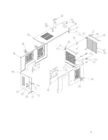
Page 8: ...8 Fig 3 2B Fig 3 2C A B C D E F G H I A B C D...

Page 9: ...DC charging system and will maintain the charge on the 12 Volt battery in the power unit WARNING NEVER INSPECT PRESSUREIZED HOSES COUPLERS OR FITTINGS WITH HANDS OR AT CLOSE DISTANCES PRESSURIZE FLUID...

Page 10: ...NNECT SWITCH ON DOING SO COULD TRIP THE BREAKER OR DAMAGE THE ELECTRICAL SYSTEM OF THE POWER UNIT OR TRUCK 6 To engage the hydraulic pump move the clutch engagement lever to the in position The pressu...

Page 11: ...fittings for damage Replace components as required Once a month check the pump coupling for damage Replace as required Once a month check the voltage of the battery service as required following the...

Page 12: ...35 5 1061 OOP NUT 3 8 nc 36 6 1062 OOP NUT nc 49 7 1063 OOP LOCK WASHER 3 8 45 8 1064 OOP LOCK WASHER 43 9 3125 OOP NUT NYLOCK 5 8 NC 1 10 1078 OOP BOLT 3 8 nc x 1 2 11 1093 OOP FLAT WASHER 3 8 2 12 1...

Page 13: ...2076 OOP FUEL SENDER 1 47 2077 OOP SCREW SELF TAP 10 x 5 8 SLT HX 5 50 5197 OOP O RING 4000 12 1 51 5190 OOW SHAFT SPLINED 1 54 5189 OOP HOSE CLAMP T BOLT 2 55 1099 OOP WASHER FLAT 1 4 2 56 3458 OOP F...

Page 14: ...OUNT 1 85 5134 OOD SHROUD COVER 1 86 5135 OOD STAND OFF 7 87 5137 OOP FUEL CAP 1 88 5138 OOP MUELLER STRAINER 1 89 5136 OOW ALTERNATOR PLATE 1 90 5139 OOP PUMP 1 91 5140 OOP VALVE 1 92 5141 OOP VALVE...

Page 15: ...OOP FITTING 24 24 BEADED 1 127 5163 OOP FITTING 4 6 1 128 5164 OOP BULKHEAD NUT 1 129 4324 OOP BULKHEAD FITTING 1 130 5165 OOP FITTING 12 8 1 132 5166 OOP 1 EXHAUST CLAMP 5 16 1 133 5167 OOP 3 EXHAUST...

Page 16: ...PTO LEVER EXT 1 152 5182 OOP U BOLT 1 153 5183 OOP LATCH 3 WEATHER STRIP 220 1 154 5187 OOP PIPE PLUG 1 NPT 1 155 1382 OOP FITTING TEE 1 156 5192 OOP FITTING 6401 12 12 1 157 5188 OOP BOLT 3 8 NC X 2...

Page 17: ...17...

Page 18: ...18...

Page 19: ...19...

Page 20: ...ompletely and replace plug When replacing engine oil filter place a suitable container under the filter and remove filter Apply a film of clean oil to the gasket surface of the new filter Install new...

Page 21: ...to engine manual Water in fuel Empty water sediment trap Bleed injectors per engine manual Cold start not functioning Check current to glow plugs on cold start units Repair circuit or replace glow pl...

Page 22: ...22 SERVICE AND REPAIR NOTES...

Reviews: