background image

17- ENG

D28176

Oil

Checking

1.

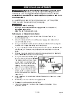
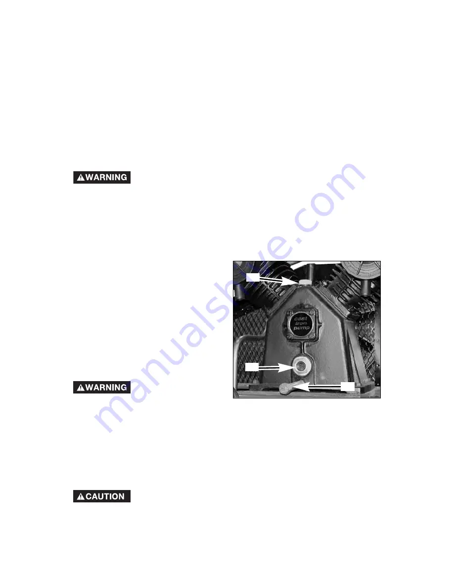
The oil level should be to the middle
of the sight glass (C).

2.

If needed remove oil fill plug (A) and
slowly add oil until it reaches the
middle of the sight glass. 

NOTE: 

Use an oil specifically formulated

for use in an air compressor, such as
Porter-Cable PAS1 air compressor oil.
Oil may be found at the store where the
air compressor was purchased.

Changing

Drain tank to release
air pressure before

removing the oil fill cap or oil drain
plug.

1.

Remove the oil fill plug (A). 

2.

Remove the oil drain plug (B) and drain oil into a suitable container. 

3.

Replace the oil drain plug (B) and tighten securely 

4.

Slowly add compressor oil until it reaches the middle of the sight glass (C).

NOTE:

When filling the crankcase, the oil flows very slowly into the pump.

If the oil is added too quickly, it will overflow and appear to be full. 

NOTE:

Crankcase oil capacity is approximately 29 fluid ounces (857,6 ml).

Overfilling with oil will cause premature compressor
failure. Do not overfill.

5.

Replace oil fill plug (A) and tighten securely.

To Drain Tank

NOTE:

Operation of the air compressor will cause condensation to build up in

the air tank. Always drain tank on a washable surface or into a suitable
container to prevent damaging or staining surfaces.
1.

Set the On/Auto/Off lever to “OFF”.

2.

Close the globe valve.

3.

Remove the air tool or accessory.

4.

Open the globe valve and allow the air to slowly bleed from the air tank
until tank pressure is approximately 20 psi. 

5.

Close the globe valve.

6.

Drain water from air tank by opening drain valve (counter-clockwise) on
bottom of tank.

Water will condense in the air tank. If not drained, water
will corrode and weaken the air tank causing a risk of air
tank rupture.

7.

After the water has been drained, close the drain valve (clockwise).  The air
compressor can now be stored.

NOTE

: If drain valve is plugged, release all air pressure.  The valve can then be

removed, cleaned, then reinstalled.

C

B

A

Summary of Contents for C7510

Page 1: ...nstructions before starting operations Part No D28176 049 1 ESPA OL P GINA 29 FRAN AIS PAGE 57 To learn more about Porter Cable visit our website at http www porter cable com Model C7510 Copyright 200...

Page 2: ...the symbols below Please read the manual and pay attention to these symbols IMPORTANT SAFETY INSTRUCTIONS Some dust created by power sanding sawing grinding drilling and other construction activities...

Page 3: ...roperty damage To reduce the risk of fire do not allow the compressor to operate unattended Always operate the compressor in a well ventilated area free of combustible materials gasoline or solvent va...

Page 4: ...ndensed water from tank causing rust and thinning of the steel tank Modifications or attempted repairs to the tank Unauthorized modifications to the unloader valve safety valve or any other components...

Page 5: ...ect voltage and adequate fuse protection The compressed air directly from your compressor is not safe for breathing The air stream may contain carbon monoxide toxic vapors or solid particles from the...

Page 6: ...thing WARNING Risk of Falling A portable compressor can fall from a table workbench or roof causing damage to the compressor and could result in serious injury or death to the operator Always operate...

Page 7: ...parts WARNING Risk of Unsafe Operation Unsafe operation of your air compressor could lead to serious injury or death to you or others HAZARD WARNING Risk of Serious Injury or Property Damage When Tran...

Page 8: ...ectricity from electrical panel to outlet DUTY CYCLE This air compressor pump is capable of running continuously To prolong the life of the air compressor run it at a 50 75 duty cycle air compressor p...

Page 9: ...ankcase Serious damage can result from even limited operation unless filled with oil and broken in correctly Make sure to closely follow initial start up procedures Multi Viscosity motor oils like 10W...

Page 10: ...eded solid shims may be placed between the washers and floor to evenly distribute weight on all four feet 6 Place the 4 3 8 lag screws through the air compressor feet washers shims and into the anchor...

Page 11: ...the motor nameplate on side of motor for this information NOTE The wiring must be the same as the motor nameplate voltage plus or minus 10 Refer to local codes for recommended wire sizes correct wire...

Page 12: ...nsation can gather and freeze Apply pressure before underground lines are covered to make sure all pipe joints are free of leaks A flexible coupling is recommended to be installed between the air disc...

Page 13: ...d separately Opens and closes air discharge valve Turn knob counter clockwise to open and clockwise to close Drain Valve The drain valve is located at the base of the air tank and is used to drain con...

Page 14: ...not closely followed This procedure is required before the air compressor is put into service and when the check valve or a complete compressor pump has been replaced 1 Make sure the On Auto Off leve...

Page 15: ...l ventilated areas free of gasoline or other combustible vapors If the compressor is being used to operate a sprayer DO NOT place compressor near the spray area Before Each Start Up 1 Place On Auto Of...

Page 16: ...extremely dirty and or hostile environment will require a greater frequency of all maintenance checks Unit cycles automatically when power is on When performing maintenance you may be exposed to volt...

Page 17: ...pacity is approximately 29 fluid ounces 857 6 ml Overfilling with oil will cause premature compressor failure Do not overfill 5 Replace oil fill plug A and tighten securely To Drain Tank NOTE Operatio...

Page 18: ...ounting screws enough to hold the motor in place for checking pulley and flywheel alignment Belt Replacement Refer to the Parts Manual for replacement belt part number Serious injury or damage may occ...

Page 19: ...urn air compressor off lock out the power supply and relieve all air pressure from the air tank 2 Remove belt guard 3 Place a straightedge against the outside of the flywheel and the motor drive pulle...

Page 20: ...rom the air tank 2 Apply a soap solution to all air line fittings and connections piping 3 Correct any leaks found IMPORTANT Even minor leaks can cause the air compressor to overwork resulting in prem...

Page 21: ...and pump Carefully move outlet tube away from check valve 4 Using an adjustable wrench loosen pressure relief tube nut at air tank and pressure switch Carefully move pressure relief tube away from che...

Page 22: ...anual is not recommended If additional service is required contact your nearest Authorized Warranty Service Center Reset Button STORAGE Before you store the air compressor make sure you do the followi...

Page 23: ...ttings where air can be heard escaping Check fittings with soapy water solution DO NOT OVERTIGHTEN Air leaks at fittings Air leaks at pressure switch release valve if equipped Defective pressure switc...

Page 24: ...filter removed Refer to the Air Filter paragraph in the Maintenance section Pressure reading on the regulated pressure gauge if equipped drops when an accessory is used It is normal for some pressure...

Page 25: ...load switch will automatically reset Tank pressure exceeds pressure switch cut in pressure Motor will start automatically when tank pressure drops below cut in pressure of pressure switch Loose electr...

Page 26: ...Carbon build up in pump Have checked by a Trained Service Technician Belt to tight Check belt tension see Adjusting Belt Tension in the Maintenance section Excessive belt wear Loose belt Tight belt Lo...

Page 27: ...27 ENG D28176 NOTES...
Page 28: ...essors with 60 and 80 gallon tanks will be inspected at the site of installation Contact the nearest Porter Cable Authorized Warranty Service Center that provides on site service calls for service cal...

Reviews: