background image

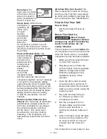
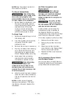
Drain Valve: 

The 

drain valve is located 

at the base of the air  

tank and is used to 

drain condensation at 

the end of each use.

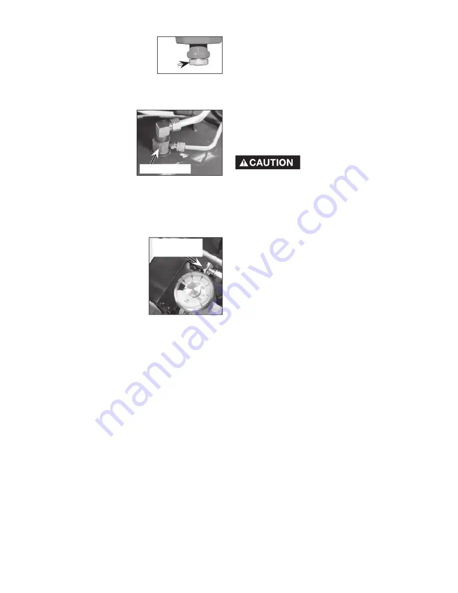
Check Valve:  

When the air 

compressor is 

operating, the 

check valve 

is "open", 

allowing 

compressed 

air to enter 

the air tank.  

When the 

air compressor reaches "cut-out" 

pressure, the check valve "closes", 

allowing air pressure to remain inside 

the air tank. 

Pressure Release Valve: 

 The 

pressure release 

valve located on 

the side of the 

pressure switch, 

is designed to 

automatically 

release 

compressed 

air from the 

compressor head 

and the outlet tube when the air 

compressor reaches "cut-out" pressure 

or is shut Off. The pressure release 

valve allows the motor to restart freely. 

When the motor stops running, air will 

be heard escaping from this valve for a 

few seconds.  No air should be heard 

leaking when the motor is running 

or after the unit reaches "cut-out" 

pressure.

Motor Overload Protector (not 

shown): 

The motor has an automatic 

reset thermal overload protector. If 

the motor overheats for any reason, 

the overload protector will shut 

Off the motor.  The motor must 

be allowed to cool down before 

restarting.  The compressor will 

automatically restart after the motor 

cools.

12 - ENG

A09770

Check Valve

Before First Start Up 

Risk of Unsafe 

Operation. Serious 

damage may result if the following 

break-in instructions are not  

closely followed.

This procedure is required 

before

 the 

air compressor is put into service and 
when the check valve or a complete 
compressor pump has been replaced.
1.  Make sure the On/Auto/Off lever 

is in the "Off" position.

2.  Plug the power cord into the 

correct branch circuit receptacle. 
(Refer to Voltage and Circuit 
Protection paragraph in the 
Installation section of this 
manual.)

3.  Open the drain valve (counter-

clockwise) fully to permit air to 
escape and prevent air pressure 
build up in the air tank during the 
break-in period.

4.  Move the On/Auto/Off lever 

to "On/Auto" position. The 
compressor will start.

5.  Run the compressor for 15 

minutes. Make sure the drain 
valve is open and there is 
minimal air pressure build-up in 
tank.

6.  After 15 minutes, close the drain 

valve by turning clockwise. The 
air receiver will fill to "cut-out" 
pressure and the motor will  
stop. 

The compressor is now ready for use.

Pressure 

Release Valve

How to Use Your Unit

How to Stop:

1.  Set the On/Auto/Off lever to 

"Off".

Drain 
Valve

Air Intake Filter (not shown):

 This 

filter is designed to clean air coming 

into the pump. This filter must always 

be clean and ventilation openings free 

from obstructions. See "Maintenance".

Summary of Contents for CFFC350C

Page 1: ...__________________________ Serial No ______________________________________ IMPORTANT Please make certain that the person who is to use this equipment carefully reads and understands these instruction...

Page 2: ...the symbols below Please read the manual and pay attention to these symbols IMPORTANT SAFETY INSTRUCTIONS Some dust created by power sanding sawing grinding drilling and other construction activities...

Page 3: ...roperty damage To reduce the risk of fire do not allow the compressor to operate unattended Always operate the compressor in a well ventilated area free of combustible materials gasoline or solvent va...

Page 4: ...ndensed water from tank causing rust and thinning of the steel tank Modifications or attempted repairs to the tank Unauthorized modifications to the unloader valve safety valve or any other components...

Page 5: ...ect voltage and adequate fuse protection The compressed air directly from your compressor is not safe for breathing The air stream may contain carbon monoxide toxic vapors or solid particles from the...

Page 6: ...thing WARNING Risk of Falling A portable compressor can fall from a table workbench or roof causing damage to the compressor and could result in serious injury or death to the operator Always operate...

Page 7: ...parts WARNING Risk of Unsafe Operation Unsafe operation of your air compressor could lead to serious injury or death to you or others HAZARD WARNING Risk of Serious Injury or Property Damage When Tran...

Page 8: ...s is called cut in pressure Cut Out Pressure When an air compressor is turned on and begins to run air pressure in the air tank begins to build It builds to a certain high pressure before the motor au...

Page 9: ...ian GROUNDING INSTRUCTIONS Risk of Electrical Shock In the event of a short circuit grounding reduces the risk of shock by providing an escape wire for the electric current This air compressor must be...

Page 10: ...OT USE 14 OR 16 AWG Voltage and Circuit Protection Refer to the specification chart for the voltage and minimum branch circuit requirements Certain air compressors can be operated on a 15 amp circuit...

Page 11: ...mp not shown Compresses air into the air tank Working air is not available until the compressor has raised the air tank pressure above that required at the air outlet Description of Operation Become f...

Page 12: ...art after the motor cools 12 ENG A09770 Check Valve Before First Start Up Risk of Unsafe Operation Serious damage may result if the following break in instructions are not closely followed This proced...

Page 13: ...t valves Risk of Unsafe Operation Unit cycles automatically when power is on When servicing you may be exposed to voltage sources compressed air or moving parts Before servicing unit unplug or disconn...

Page 14: ...sion 1 Before starting compressor pull the ring on the safety valve to make sure that the safety valve operates freely If the valve is stuck or does not operate smoothly it must be replaced with the s...

Page 15: ...D ADJUSTMENTS Risk of Unsafe Operation Unit cycles automatically when power is on When servicing you may be exposed to voltage sources compressed air or moving parts Before servicing unit unplug or di...

Page 16: ...nnect Orient outlet pressure gauge to read correctly Tighten connect with wrench To Replace Regulator 1 Release all air pressure from air tank See To Drain Tank in the Maintenance section 2 Unplug uni...

Page 17: ...is approximately 20 psi Release safety valve ring 6 Drain water from air tank by opening drain valve on bottom of tank Risk of Bursting Water will condense in the air tank If not drained water will co...

Page 18: ...tight enough Tighten fittings where air can be heard escaping Check fittings with soapy water solution Do Not Overtighten Air leaks at fittings Air leaks at pressure switch release valve Defective pre...

Page 19: ...essor is not supplying enough air to operate accessories Prolonged excessive use of air Compressor is not large enough for air requirement Hole in hose Check valve restricted Air leaks Restricted air...

Page 20: ...ch will automatically reset Tank pressure exceeds pressure switch cut in pressure Motor will start automatically when tank pressure drops below cut in pressure of pressure switch Extension cord is wro...

Page 21: ...21 ENG A09770 NOTES...
Page 22: ...purchaser Air compressors with 60 and 80 gallon tanks will be inspected at the site of installation Contact the nearest Porter Cable Authorized Warranty Service Center that provides on site service c...

Reviews: