background image

8

USING THE TOOL

Complete all steps of PREPARING THE TOOL before using the tool.

To fire, grip tool firmly, position nose of tool onto work surface, push forward
on tool to depress safety, and squeeze trigger to fire a fastener. This “trigger
fire” method provides the most accurate fastener placement. This tool is
shipped from the factory with a “restrictive fire trigger” that only allows the tool
to be fired this way and is less likely to fire an unwanted fastener.

An alternate “bottom fire trigger” is available. The “bottom fire” trigger allows
the tool to be fired in two different ways.

1. The tool can be fired using the “trigger fire” method described above.

OR

2. Grip tool firmly, depress and hold trigger while pushing the tool firmly
against work surface. The tool will fire a fastener each time the safety is
depressed. This method is known as “bottom fire” and allows very fast
repetitive fastener placement.

The “bottom fire trigger” is available free-of-charge by calling 1-800-321-9443
in the United States and Canada or 001-731-660-9374 outside the United
States and Canada, and providing tool model and serial number. For
identification purposes: the Bottom Fire Trigger is black and the Restrictive Fire
Trigger is red.

WARNING: 

Remove finger from trigger when not driving fasteners.

Never carry tool with finger on trigger: tool will fire a fastener if safety
is bumped.

WARNING:

Keep tool pointed in a safe direction at all times.

WARNING:

Never attempt to drive a fastener into material that is too

hard, or at too steep an angle, or near the edge of the workpiece. The
fastener can ricochet causing personal injury.

WARNING:

Disconnect tool from air supply before performing

maintenance, clearing a jammed fastener, leaving work area, moving
tool to another location, or handing the tool to another person.

WARNING:

Clean and inspect tool daily. Carefully check for proper

operation of trigger and safety mechanism. 

Do Not

use the tool unless

both the trigger and the safety mechanism are functional, or if the tool
is leaking air or needs any other repair.

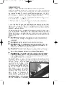
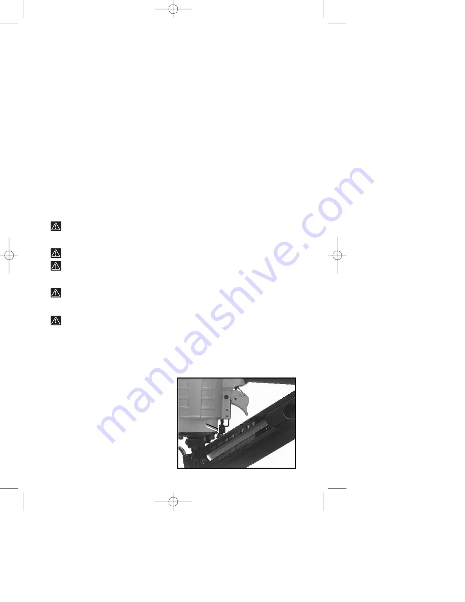
The depth to which a fastener is driven is controlled by the depth adjustment
knob (A) Fig. 19. The depth of drive is factory adjusted to a nominal setting.
Test fire a fastener and check depth. If a change is desired, rotate the
adjustment knob (A) Fig. 19: the
adjustment knob has detents every 

1

/

4

turn. Rotate the knob clockwise (see
Fig. 19), to increase the depth of
drive, rotate the knob counterclock-
wise to decrease the depth of drive.
Test fire another fastener and check
depth. Repeat as necessary to
achieve desired results. The amount
of air pressure required will vary
depending on the size of the fastener
and the material being fastened.

Fig. 19

A

903090 - 06-30-01.qxd  9/25/02  1:53 PM  Page 8

Summary of Contents for DA250A

Page 1: ...____________________ Serial No _______________________________________ IMPORTANT Please make certain that the person who is to use this equipment carefully reads and understands these instructions bef...

Page 2: ...Cable Corporation 4825 Highway 45 North Jackson TN 38305 Date of Manufacture ___________________________ Fecha de fabricaci n Date de fabrication Serial No ______________________________________ N mer...

Page 3: ...tic side shields These safety glasses must conform to ANSI Z87 1 requirements approved glasses have Z87 printed or stamped on them Fig 1 2 WEAR EAR PROTECTION to safe guard against possible hearing lo...

Page 4: ...Porter Cable Service Center for a replacement Fig 6 13 ONLY USE PARTS FASTENERS AND ACCESSORIES recommended by Porter Cable 14 REMOVE ALL FASTENERS from tool before connecting to air supply The tool...

Page 5: ...kpiece The workpiece is likely to split allowing the fastener to fly free or ricochet causing personal injury Fig 12 23 KEEP HANDS AND BODY PARTS away from area shown in Fig 13A to avoid injury 24 DO...

Page 6: ...lter will remove most of these contaminates and significantly prolong the life of the tool If an in line oiler is not available place five or six drops of Porter Cable Air Tool Oil see ACCESSORIES int...

Page 7: ...ils with points down see Fig 15 and align with the magazine T slot 3 Feed the strip of nails into the magazine T slot until they are past the stop A Fig 16 4 Pull the follower B Fig 17 all the way to...

Page 8: ...ing fasteners Never carry tool with finger on trigger tool will fire a fastener if safety is bumped WARNING Keep tool pointed in a safe direction at all times WARNING Never attempt to drive a fastener...

Page 9: ...moving or re installing rubber cushion CLEARING A JAMMED FASTENER 1 WARNING Disconnect tool from air supply 2 Remove any remaining fasteners from the nailer A Place finger through hole A Fig 20 and pu...

Page 10: ...against defective material and workmanship We cannot guarantee repairs made or attempted by anyone other than these agencies Should you have any questions about your tool feel free to write us at any...

Page 11: ...oduct CATALOG QTY NUMBER DESCRIPTION LENGTH GAUGE BOX DA15125 16 Ga D A Nail 11 4 11 4 15 4000 DA15125 1 1000 Pk of DA15125 15 1000 DA15150 15 Ga D A Nail 11 2 11 2 15 4000 DA15150 1 1000 Pk of DA1515...

Page 12: ...r than our Service Centers or Authorized Service Stations ANY IMPLIED WARRANTY INCLUDING THE IMPLIED WARRANTIES OF MERCHANTABILITY AND FITNESS FOR A PARTICULAR PURPOSE WILL LAST ONLY FOR ONE 1 YEAR FR...

Page 13: ...pour les produits Porter Cable Delta s adresser tout distributeur Porter Cable Delta centre de service agr ou centre de service d usine Porter Cable Delta Si vous n avez acc s aucun de ces centres app...

Reviews: