10
ASSEMBLY AND ADJUSTMENTS
WARNING
!
Estimated Assembly Time: 10 - 20 minutes.
To avoid injury, always keep the plug disconnected
from the power source and the switch turned OFF
until the sander is completely assembled and
adjusted properly.
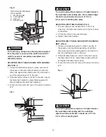
MOUNTING WORKTABLE ON DISC (FIG. A, B )
The larger worktable is used with the sanding disc. It
should be used to support workpieces in all sanding
operations except inside curve applications.
1.
Bag "E" -
Locate worktable handles (1) and washers
(2) in parts bag.
2. Place the worktable (3) onto the sander frame,
aligning the semi-circle slot (4) with the threaded
hole (5).
3. Place a washer (2) on threaded shaft of each
worktable handle (1 ), insert through semi-circular
slot (4), and tighten into threaded hole (5). Repeat on
other side of table.
4. Adjust worktable to level or any angle between 0°
and 45° for sanding.
NOTE:
Always check to make sure the handles are tight
before beginning any sanding operation.
Fig. A
To avoid trapping the workpiece or fingers between
the worktable (1) and sanding disc (2) , the
worktable edge should be positioned a maximum of
1/16 in. (1.6 mm) from sanding disc plate as shown
in Fig. B.
Fig. B
CAUTION
!
MOUNTING WORKTABLE ON BELT (FIG. C, D )
The small worktable is used with the sanding belt. It
should be used to support workpieces in all sanding
operations except inside curve applications.
1. Loosen the inner hex screw (1) using the 5 mm hex
key, and raise the belt bed (2) in the vertical position.
Tighten the inner hex screw (1).
Fig. C
2.
Bag "E" -
Locate worktable knob (3) and washer (4)
in parts bag.
3. Place the worktable (5) onto the sander frame,
aligning the semi-circle slot (6) with the threaded
hole (7).
4. Place washer (4) on threaded shaft of worktable
knob (3 ), insert through semi-circular slot (6), and
tighten into threaded hole (7).
5. Adjust worktable to level or any angle between 0°
and 45° for sanding.
Fig. D
To avoid trapping the workpiece or fingers between
the worktable and sanding belt, the worktable
edge should be positioned a maximum of 1/16 in.
(1.6 mm) from sanding belt.
7
3 4
6
5
ON
OFF
2
1
4
5
3
2 1
2
1
1
2
1
1/16 in. (1.6 mm)
CAUTION
!
Summary of Contents for PCB420SA
Page 8: ...8 UNPACKING YOUR BELT DISC SANDER ON OFF A D E B F G H C...
Page 22: ...22 NOTES...
Page 23: ...23 NOTES...


