12
To avoid trapping the workpiece or fingers between
the worktable and sanding disc, the worktable edge
should be positioned a maximum of 1/16 in.
(1.6 mm) from sanding disc plate.
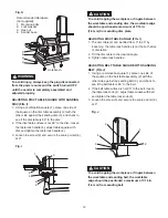
ADJUSTING DISC TABLE ANGLE (FIG. I)
1. The disc table (2) can be tilted from 0° to 45° by
loosening the table lock handles (4) at the both sides
of disc table.
2. Tilt the disc table to the desired angle.
3. Tighten table lock handles.
ADJUSTING BELT TABLE SQUARE WITH SANDING
BELT (FIG. J)
1. Using a combination square (1), place one side of
the square on the belt table assembly (2) with the
other side against the sanding belt (3), and check to
see if the belt table is 90° to the belt.
2. If the belt table surface is not 90° to the belt, loosen
the table lock knob (4), adjust table square with belt
and tighten the table lock knob (4).
3. Loosen the screw (5) and secure the scale pointer (6)
at 0°.
Fig. J
To avoid trapping the workpiece or fingers between
the worktable and sanding belt, the worktable
edge should be positioned a maximum of 1/16 in.
(1.6 mm) from sanding belt.
CAUTION
!
1
2
3
4
6
5
Fig. H
To avoid injury, always keep the plug disconnected
from the power source and the switch turned OFF
until the sander is completely assembled and
adjusted properly.
ADJUSTING DISC TABLE SQUARE WITH SANDING
DISC (FIG. I)
1. Using a combination square (1), place one side of
the square on the disc table assembly (2) with the
other side against the sanding disc (3), and check to
see if the disc table is 90° to the disc.
2. If the disc table surface is not 90° to the disc, loosen
the table lock handle (4), adjust table square with
disc and tighten the table lock handle (4).
3. Loosen the screw (5) and secure the scale pointer (6)
at 0°.
Fig. I
ON
OFF
Recommended Hardware
(not supplied)
1. Mounting bolts
2. Lock washer
3. Hex nut
4. Sander base
1
4
3
2
workbench
WARNING
!
1
2
3
4
6
5
CAUTION
!
Summary of Contents for PCB420SA
Page 8: ...8 UNPACKING YOUR BELT DISC SANDER ON OFF A D E B F G H C...
Page 22: ...22 NOTES...
Page 23: ...23 NOTES...


