16
MAINTENANCE
•
For your safety, turn switch OFF and remove
the power cord from the electrical outlet before
adjusting or performing maintenance on your
sander.
•
To avoid electric shock or fi re, all repairs to
the electrical components should be done by
a qualifi ed service technician. Before each use
check for damaged, missing, or worn parts;
check for alignment of moving parts, binding,
improper mounting, or any other conditions
that may affect the operation. Should any of
these conditions exist, do not use the sander
until properly repaired or parts are replaced.
Frequently blow or vacuum dust from all sander
parts and motor housing.
REPLACING SANDING DISC (FIG. S, T)
To avoid injury, turn switch OFF and disconnect the
plug from the power source before removing and
installing sanding belt.
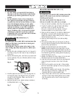
A sanding disc is pre-mounted at the factory. Use
only sanding discs that measures 8 in. (203 mm) in
diameter.
1. Remove the disc worktable (See Fig. A on page 10),
and then remove the disc cover (1) by removing six
screws (2).
2. Remove the existing disc, and clean any residue left
on disc plate (3). Only use mineral spirits to remove
this residue.
Fig. S
3. Peel the plastic (4) back from new sanding disc (5)
and carefully press sanding disc fi rmly in position
around the sanding plate. Make sure the disc is
centered on the plate.
4. Reinstall the disc cover, tighten screws and place
sanding table back on unit.
Fig. T
WARNING
!
ON
OFF
1
2
3
5
4
REPLACING SANDING BELT (FIG. U, V)
To avoid injury, turn switch OFF and disconnect the
plug from the power source before removing and
installing sanding belt.
Use only sanding belts that measures 4 in.
(102 mm) in width / 36 in. (914 mm) in length.
1. Remove the belt worktable. (See Fig. D on page 10)
2. Position the belt work support frame horizontally
as shown in Fig. U. Loosen the inner hex
screw (1) using a 5 mm hex wrench, turning it
counterclockwise. Do not remove the screw.
3. Remove the two screws (2, 3) using a phillips head
screwdriver, and pull out the tension lever (4) to
release the tension of the sanding belt (5). Remove
the belt exhaust cover (6).
4. Remove the sanding belt (5) from both sanding
drums (7).
5. Place new sanding belt over sanding drums. Make
sure the belt arrow located on the inside of the belt is
pointed in the right direction.
6. Replace the belt exhaust cover (6) in position.
NOTE:
Stretch the belt from the right side to make
top and lower side of the belt fl at and tight as shown
in Fig. V for keeping the belt exhaust cover (6) away
from interferring with the sanding belt when placing
the belt exhaust cover on.
7. Replace and tighten the two screws (2, 3) and push
the tension lever (4) in to apply belt tension.
8. Push the belt by hand and check if the sanding belt
tends running to one side or the other of the two
drums.
9. View from the switch end of sander, if the sanding
belt runs toward disc, slightly turn the tracking knob
(8) clockwise (down).
10. View from the switch end of sander, if the sanding
belt runs away from the disc, slightly turn the
tracking knob (8) counterclockwise (up).
11. Plug in the sander and turn the switch ON and OFF
quickly to check if the sanding belt moves to either
side. Re-adjust and fi ne-tune the tracking knob if
necessary.
WARNING
!
WARNING
!
Summary of Contents for PCB420SA
Page 8: ...8 UNPACKING YOUR BELT DISC SANDER ON OFF A D E B F G H C...
Page 22: ...22 NOTES...
Page 23: ...23 NOTES...


