background image

7

FINISH NAIL GUIDE ASSEMBLY

1.

WARNING: 

Disconnect tool from air supply.

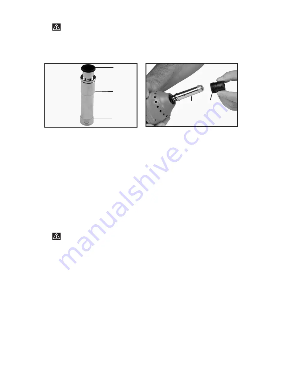
2. The finish nail guide (A) Fig. 17, for driving 1-

1

/

4

"(3d) to 2-

1

/

2

"(8d) finish

nails, is provided with a rubber nose cushion (B) Fig. 17 that will reduce
marring of the work surface. Assembly of the finish nail guide requires the
use of the magnetic nail guide bushing supplied on the tool (Fig. 15).  

3  To install finish nail guide, lay tool on its cap with nail guide pointing
upward. Loosen and remove the magnetic nail guide bushing (B) Fig. 15
using the 24mm open end wrench supplied.

4. Lift the magnetic nail guide (A) Fig. 15 off of the driver blade and place it in
the carrying case.  

5. Remove the plastic plug (C) Fig. 17 from the finish nail guide. Take care
not to allow the drive pin and spring to fall out of the bore of the finish nail
guide.  Slide the finish nail guide (A) Fig. 18 over the driver blade.

6. Slide the magnetic nail guide bushing (B) Fig. 18 over the finish nail guide
and screw it into the housing using the 24mm open end wrench and tighten
as securely as possible.

STANDARD NAIL GUIDE ASSEMBLY

1.

WARNING: 

Disconnect tool from air supply.

2. Standard (spike) nail guide  has a ¾" ID and is used for driving large  4"
(20d) to 6-

1

/

2

" (70d) common nails/spikes.

3. To install standard (spike) nail guide and bushing, lay tool on its cap with
nail guide pointing upward. Loosen and remove the magnetic nail guide
bushing (B) Fig. 15 using the 24mm open end wrench supplied.  

4. Slide the magnetic nail guide (A) Fig. 15 off of the driver blade.

5. Place both the magnetic nail guide and bushing in the carrying case for
safe storage.

6. Take the standard nail guide (A) Fig. 19 and guide bushing (B) from the
carrying case.

7. Slide the standard nail guide (A) Fig. 20 over the driver blade and inside of
the spring coils.  Slide the standard nail guide bushing (B) over the driver
blade and spring.  Screw the standard nail guide bushing into the tool
housing and tighten as securely as possible using the 24mm open end
wrench.

Fig. 17

A

B

C

Fig. 18

A

B

Summary of Contents for PN650

Page 1: ..._______________ Serial No _______________________________________ IMPORTANT Please make certain that the person who is to use this equipment carefully reads and understands these instructions before s...

Page 2: ...2 Date of Manufacture ___________________________ Fecha de fabricaci n Date de fabrication Serial No ______________________________________ N mero de serie Nombre d ordre...

Page 3: ...llow warnings could result in DEATH or SERIOUS INJURY Fig 1 2 Operator and others in work area MUST wear safety glasses with side shields These safety glasses must conform to ANSI Z87 1 requirements a...

Page 4: ...rews and caps are securely tightened Fig 8 13 Do not overreach Keep proper footing and balance at all times when using or handling the tool Fig 9 14 Fire fasteners into work surface only never into ma...

Page 5: ...le for the other three guides POWER SOURCE This tool is designed to operate on clean dry compressed air at regulated pressures between 50 and 120 PSI Pounds per Square Inch 3 4 to 8 3 BAR The preferre...

Page 6: ...tool from air supply 2 The magnetic nail guide A Fig 14 for driving 6d to 16d common flat head nails comes assembled on the tool To change attachments proceed as follows 3 Lay the tool on its cap wit...

Page 7: ...guide bushing B Fig 18 over the finish nail guide and screw it into the housing using the 24mm open end wrench and tighten as securely as possible STANDARD NAIL GUIDE ASSEMBLY 1 WARNING Disconnect to...

Page 8: ...e carrying case for safe storage 3 Slide hammer sleeve A Fig 23 over the driver blade E 4 Screw the hammer head guide bushing B Fig 24 into the housing using the 30mm open end wrench supplied in the c...

Page 9: ...ways wear ANSI Z87 1 approved safety glasses and hearing protection when preparing or operating the tool Never use a tool that is leaking air has missing or damaged parts or requires repair OPERATION...

Page 10: ...stener MAINTENANCE CLEAN AND INSPECT DAILY WARNING Disconnect tool from air supply before cleaning and inspection Correct all problems before placing the tool back in use Wipe tool clean and inspect f...

Page 11: ...valve to the closed position disconnect the air supply and sharply impact the tool cap against a piece of wood Connect the air supply hose The air pressure will seat the valve in the close position 3...

Page 12: ...ted or made by other than our Service Centers or Authorized Service Stations ANY IMPLIED WARRANTY INCLUDING THE IMPLIED WARRANTIES OF MERCHANTABILITY AND FITNESS FOR A PARTICULAR PURPOSE WILL LAST ONL...

Page 13: ...t accessoires pour les produits Porter Cable Delta s adresser tout distributeur Porter Cable Delta centre de service agr ou centre de service d usine Porter Cable Delta Si vous n avez acc s aucun de c...

Reviews: