background image

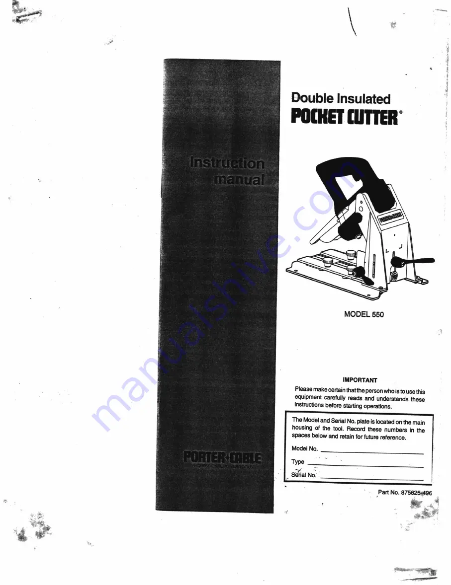
MODEL 550

IMPORTANT

Pleasemake

certain

thatthe

person

whois

to

usethis

equipment

carefully reads and

understands

these

instructions

before

starting

operations.

Spaces

below

and retain

for

future reference.

Model

No.

Type

__

-T séfial

No:

|

|

:

os

Part

No.

8756254496

_f

.

5 ; ie

é

e h

g e

L S

a

“ < c

c i l :

Summary of Contents for Pocket Cutter 550

Page 1: ...thatthepersonwhois tousethis equipment carefully reads and understands these instructions beforestarting operations Spaces belowand retainfor future reference ModelNo Type __ T s fialNo os PartNo 8756...

Page 2: ...ed repairmen Contact the nearest Porter CableService Center or other competent repair center Yt 136 3 Be Cow Ne 134 eo 193 Nx139 140 157 74 7105 100D M a 106 eo oO 107 9g 128 129 BS a Se 63 PARTS LIST...

Page 3: ...sher Column N u t Lockwasher Knob Washer L e v e r Fence P l a t e I n d e x L a b e l E C l i p Guide P i n E c c e n t r i c S h a f t N u t Lockwasher S c r e w C o r d Clamp S p r i n g M o t o r...

Page 4: ...ordoryank ittodisconnect from receptacle Keepcordfrom heat oil andsharp edges Havedamaged or worm power cord and strain reliever replaced immediately DO NOT ATTEMPT TO REPAIR POWERCORD 11 SECUREWORK U...

Page 5: ...ly damage the tool EXTENSIONCORD SELECTION Ifan extensioncord is used makesuretheconductorsize is largeenoughto prevent excessive voltage drop which will cause lossof power and possible motor damage A...

Page 6: ...can result in damage to Pocket Cutter 5 Engagethetransportlockinthe DOWNpositionbeforemovingorstoring the Pocket Cutter TO ENGAGE Push motor unit down against the motor Stop screw see Fig 3 and hold...

Page 7: ...sure cutting edge does not contact any part of the machine ADJUST WORK CLAMP CAUTION DISCONNECT MACHINE FROM POWER CIRCUIT CAUTION Tilt motor to the up position and engage transport lock _ 1 Rotateth...

Page 8: ...e Pocket Cutter base 3 Place a piece of scrap material same width as planned work onto the Pocket Cutter base and align the LEFTside of the material see Fig 8 with theLEFTribindex correspondingtomater...

Page 9: ...ick the step on the setting gage same gage used to set DEPTH OF CUT thatcorrespondstothe materialthicknessthatthework clamp issetfor 4 Position the gage under the guide bushing so that the bottom of t...

Page 10: ...testingofthistool hasbeenaccomplishedwiththefollowingaccessories Forsafestoperation it is recommendedthat onlythese accessoriesbe used with this product WARNING Since accessories other than those list...

Page 11: ...4 263 1238 Cleveland44125 Phone 216 447 9030 Fax 216 447 3097 PENNSYLVANIA Philadelphia 19154 12285McNulty Road Phone 215 677 7800 Fax 215 677 9908 TEXAS Dallas75220 10720N Stemmons Freeway Phone 214...

Reviews: