background image


5

 
H4 

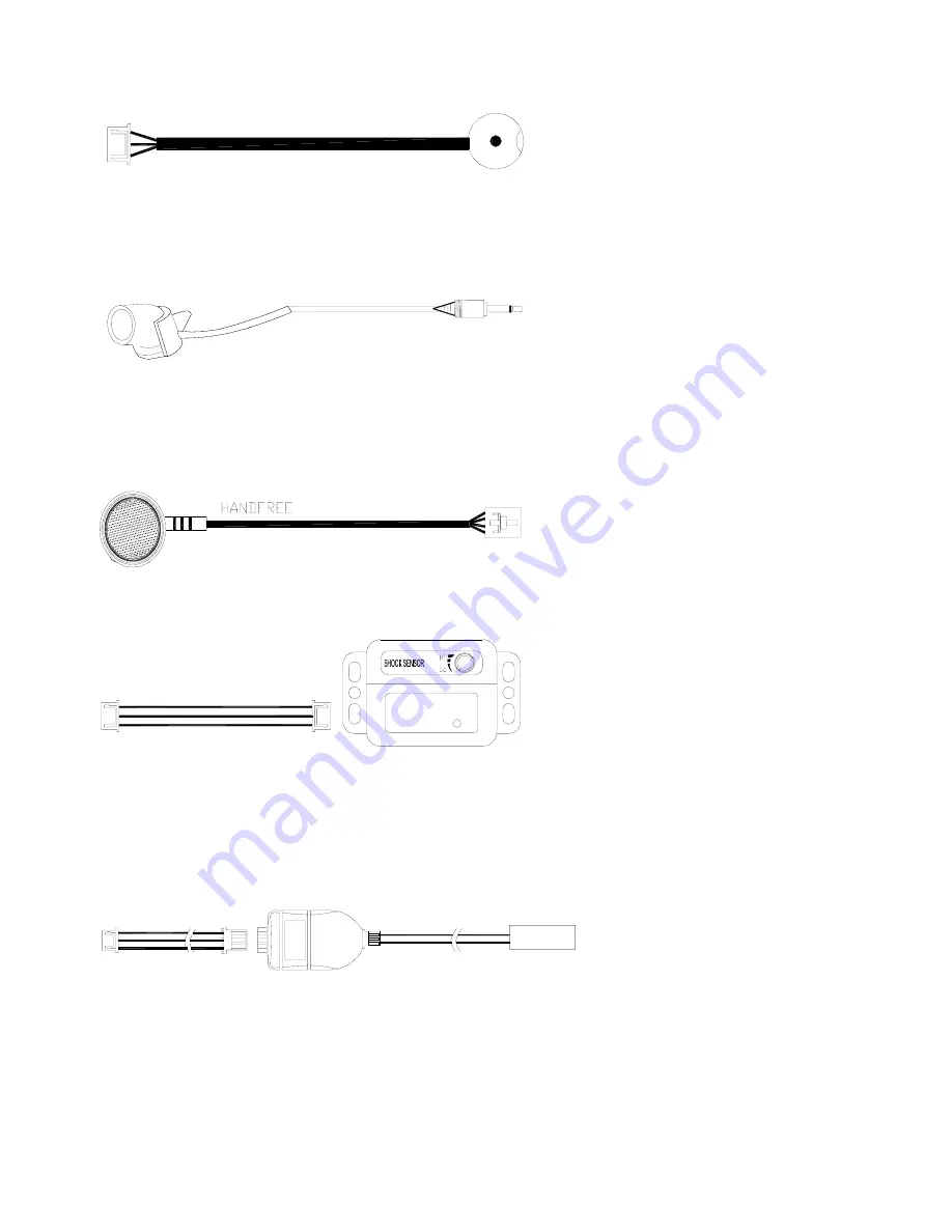
LED+VALET switch port: black 3-pin connector. (Be used in GV8300; GT8000N; GT8005N; GT8010N)


Led & Valet Switch


H5 

PC setup port: white 4-pin connector. 


H6 

MICROPHONE (be used in GV8100N; GV8200N; GV8300) 


H7 

Hs100 port: blue 4-pin connector. (optional)


H8 

Hand free (be used in GV8100N; GV8200N; GV8300)


H9 

Shock sensor or Ultrasonic sensor port: white 3-pin connector. (Be used in GT8010N; optional)


Shock Sensor


H10 

RF antenna (be used in GT8010N)


H11 

Temperature sensor port: 

blue

 3-pin connector. 

(Optional)


O PT IO N A L

T E M PE R A T U R E   SE N SO R


H12 

TL sensor port: red 3-pin connector. 

(Be used in GT8005N; optional)


H13 

GPS output port: red 2-pin connector.


Summary of Contents for GV8300

Page 1: ...1 GPS GPRS CAR ALARM GV8300 INSTALLATION MANUAL ...

Page 2: ...H1 3 Black wire connect to the ground of the vehicle The wire connects the system ground This is main ground connection of GV8300 Do not connect this wire to any existing ground wires supplied by the factory wire loom make the connection to the vehicle s frame directly H1 4 Brown wire Negative Door Switch Sensing Input Brown Negative Trigger This wire is the ground trigger input wire for negative ...

Page 3: ...oor locking See the drawing below H1 10 Orange Blue wire Lock NC H1 9 H1 10 H1 11 H1 20 H1 21 H1 22 connect to the central door locking See the drawing below H1 11 Brown Blue wire lock NO H1 9 H1 10 H1 11 H1 20 H1 21 H1 22 connect to the central door locking See the drawing below H1 14 Red wire Red wire System power 12V Constant The RED wire supplies power to the system Connect this to a constant ...

Page 4: ... the central door locking See the drawing below 1 FOR VEHICLES WITHOUT DRIVER SIDE LOCKING MOTOR 12V UNLOCK LOCK ORANGE GREEN GREEN WHITE ORANGE BLUE BROWN GREEN BLUE WHITE BROWN BLUE NO COM NC NO COM NC GREEN BLUE VAE 3602 ACTUATOR COMMON ORANGE BLUE NO COM NC ACTUATOR CONTROL SWITCH GREEN WHITE ORANGE GREEN BROWN GREEN NO COM NC UNLOCK 2 FOR VEHICLES WITH NEGATIVE CENTRAL LOCKING REF DRAWING BEL...

Page 5: ...ND BROWN GREEN 12V ORANGE GREEN GREEN WHITE BLUE WHITE ORANGE BLUE UNLOCK CUT ACTUATOR CONTROL SWITCH LOCK UNLOCK CUT 4 FOR VEHICLE WITH DIRECT SWITCHING CENTRAL LOCKING NO COM NC NO COM NC LOCK UNLOCK 12V ORANGE GREEN BLUE WHITE ORANGE BLUE GREEN WHITE BROWN GREEN BROWN BLUE CUT PASSENGER SIDE DRIVER SIDE H2 2 Key pad port black 4 pin connector Be used in GV8100N LED Button 1 Button 2 H3 12 Key p...

Page 6: ... blue 4 pin connector optional H8 Hand free be used in GV8100N GV8200N GV8300 H9 Shock sensor or Ultrasonic sensor port white 3 pin connector Be used in GT8010N optional Shock Sensor H10 RF antenna be used in GT8010N H11 Temperature sensor port blue 3 pin connector Optional OPTIONAL TEM PERATURE SENSOR H12 TL sensor port red 3 pin connector Be used in GT8005N optional H13 GPS output port red 2 pin...

Page 7: ...CUT LOCK CUT UNLOCK 12V 4 FOR VEHICLE WITH DIRECT SWITCHING CENTRAL LOCKING 12V BROWN BLUE BLUE WHITE ORANGE BLUE BROWN GREEN GREEN WHITE ORANGE GREEN NO COM NC NO COM NC UNLOCK LOCK CUT GND VEHICLE CL CONTROL BOX UNLOCK TRUNK 12V RELAY 12V 1N5401 1N5401 CENTRAL LOCKING INTERFACE CONNECTIONS 2 FOR VEHICLES WITH NEGATIVE CENTRAL LOCKING REF DRAWING BELOW GREEN NO COM NC NO COM NC BROWN BLUE BLUE WH...

Page 8: ...rference to radio or television reception which can be determined by turning the equipment off and on the user is encouraged to try to correct the interference by one or more of the following measures You are cautioned that changes or modifications not expressly approved by the party responsible for compliance could void your authority to operate the equipment Operation is subject to the following...

Reviews: