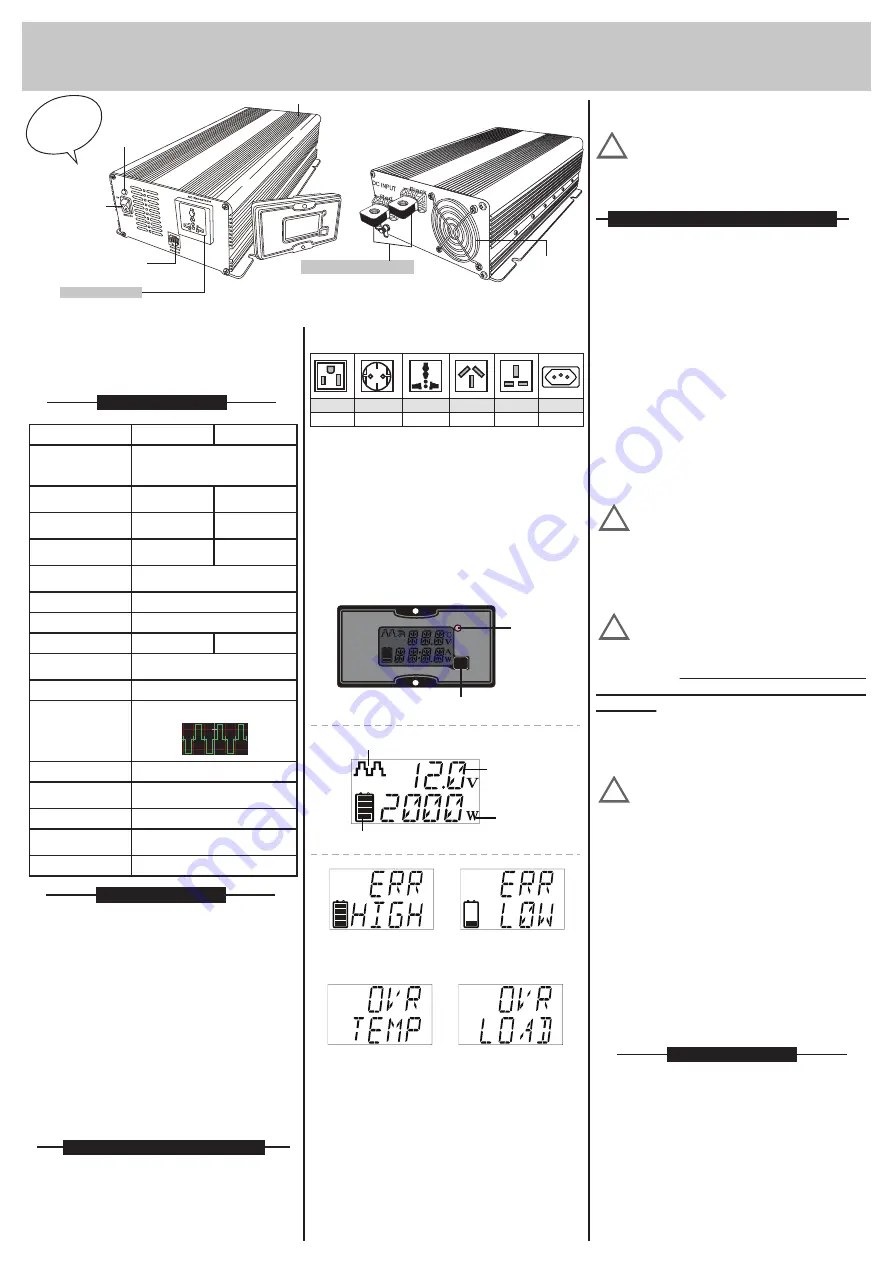
3. Rear view:
a. Ventilation window:
Do not obstruct, allow at least 15cm for airflow.
b. Battery terminals:
Connect to 12V/24V battery or other 12V/24V
power source. "+" is positive, "-" is negative.
Reverse polarity connection will blow internal
fuse and may damage inverter permanently.
c. Chassis ground lug:
HT-E-152A2
M-2000
2.Remote Control (optional):
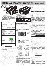
DC to AC
Power inverter
manual
Firstly, thank you for purchase our product.
Please read this manual carefully before
installing or using this product.
The power inverter series are the member
of the most advanced line of mobile AC power
systems available.
This model is used in a wide range of application
including remote homes, RVs, sailboats and
powerboats. It will operate most televisions
and VTR's, personal computers, small appliances
and tools such as drills, sanders, grinders,
mixers and blenders.
To get the most out of the power inverter, it
must be installed and used properly.
Please read the instructions in this manual
before installing and using this model.
1. Front view
a. ON/OFF switch:
Leave in the OFF position during installation.
Outlet sockets available:
type2
type3
type4
type5
type6
USA
EUROPE
UK
type11
BRAZILIAN
UNIVERSAL AUSTRALIA
If you would like to quick hook-up the power
inverter and check its performance before going
ahead with your installation, please follow these
guideline
1. Unpack and inspect the power inverter, check
to see that the power switch in the OFF position.
2. Connect the cables to the power input terminals
on the rear panel of power inverter. The red
terminal is positive (+) and black terminal is
negative (-).
Connect the cables into the terminals and tighten
the wing nut to clamp the wires securely.
3. Connect the cable from the negative terminal
of the inverter to the negative terminal of the
power source. Make a secure connection.
CAUTION!!
Loosely tightened connectors result in
excessive drop and may cause overheated
wires and melted insulation.
4. Before proceed further, carefully check if the
terminals connect correctly.
CAUTION!!
Reverse polarity connection will blow a
fuse in inverter and may permanently damage
the inverter.
Damage caused by reverse
polarity connection is not covered by our
warranty.
5. Connect the cable from the positive terminal
of inverter to the positive terminal of the power
source. Make secure connection.
WARNING!!
You may observe a spark when you make
this connection since current may flow to charge
capacitors in the power inverter.
Do not make this connection in the presence of
flammable fumes, explosions or fire may result.
6. Set power inverter switch to OFF position,
the indicator lights may blink and the internal
alarm may sound momentarily. This is normal.
Plug the test load into the AC receptacle on the
front panel of the inverter. Leave the test load
switch off.
7. Set power inverter switch to the ON position
and turn the test load on, the inverter should
supply power to the load.
Introduction
Specification
Name and Main function
Installation
1. Where to install
The power inverter should be installed in a location
that meets the following requirements:
a. Dry -
Do not allow water to drip or splash on
the inverter.
b. Cool -
Ambient air temperature should be
between -15°C and 45°C, the cooler environment
is better.
c. Ventilated -
Allow at least 15cm of clearance
around the inverter for airflow.
Ventilation
window
Battery terminals
Rear view
Connect to battery or other power source.
"+" is positive (Red),
"-" is negative (Black).
Reverse polarity connection will blow internal
fuse and may damage inverter permanently.
b. AC outlet:
!
!
!
fault LED
Indicator
ON/OFF switch
High battery
volt protection.
Low battery
volt protection.
Overload
Over temperature
Waveform
Battery volt
Load watts
Battery capacity
The ON/OFF switch turns the control circuit in
the power inverter on and off.
When the switch is in the OFF position, the power
inverter draws no current from battery. When
the switch is in the ON position but with no load,
the power inverter draws less than 600mA
(12V version) or 300 mA (24V version) from
battery.
Connect to earth ground or to vehicle chassis.
WARNING!!
Operation of the inverter without a proper
ground connection may result in an electrical
safety hazard.
!
Quick hook - up and testing
Output Frequency
Over Temperature
protection
Dimensions
(L×W×H)(by mm)
Output power
continuous
AC Output Voltage
Regulation
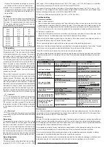
Input high voltage
shut-down
Efficiency
Overload protection
Net weight (by Kgs)
No load current draw
2000W
±8%(100:±10%)
Input low voltage
alarm
DC10.5V±0.5V
DC16V±0.5V
DC21V±1V
DC32V±1V
Input low voltage
shut-down
DC10V±0.5V
DC20V±1V
50/60Hz ±3%
YES
Output reverse
protection
YES
Cooling fan
YES
55°C ±5°C
435*179*88.5
3.7
>85%
AC100V
AC120V
AC230V
Model No.
Output wave
0.4 A(12V)
HT-E-2000-12 HT-E-2000-24
Modified Sine Wave
0.2 A(24V)
Power LED
Front view
SWITCH
ON/OFF
Case
POWE
Remote
Control
It is suitable for Australia,New Zealand, Canada,
America, Europe, Japan and Universal type.
AC receptacle


