background image


FUDA2-S1x21 Series Panel PC  

(10.4

”/12.1”/15”/17”/19”) 


Slim and Fan-less Projective Capacitive Touch Panel PC with 

Wide Temperature and Panel Mount Support 

Powered by Intel

®

 Atom

™ Bay Trail Quad-core Processor 


User's Manual 


Version 1.0 


Copyright ©  Portwell, Inc., 2016. All rights reserved. 

All other brand names are registered trademarks of their respective owners.

Summary of Contents for FUDA2-S1 21 Series

Page 1: ...e Capacitive Touch Panel PC with Wide Temperature and Panel Mount Support Powered by Intel Atom Bay Trail Quad core Processor User s Manual Version 1 0 Copyright Portwell Inc 2016 All rights reserved...

Page 2: ...ni PCIe module Installation 2 12 2 6 CF and SD card Installation 2 13 2 7 Getting Started 2 13 2 8 I O Interfaces 2 14 2 8 1 Front View 2 14 2 8 2 Rear View 2 15 2 8 3 Top View 2 16 2 8 4 Side View 2...

Page 3: ...advanced BIOS performance and update new BIOS In addition POST checkpoint list will give users some guidelines of trouble shooting Chapter 5 Important Instructions Indicate some instructions which mu...

Page 4: ...Preface Revision History Revision Date Details of Change s V1 0 2017 4 19 Initial Release...

Page 5: ...ibility FUDA2 Panel PC s application oriented design provides customers an ideal HMI solution for factory automation applications Thanks to its robustness and easy operation Panel PC with projective c...

Page 6: ...A2 S1221 15 FUDA2 S1521 17 FUDA2 S1721 19 FUDA2 S1921 Screws for HDD installation M3X4L Screw 4 pieces Driver CD 3 pin Terminal Block Connector Female Optional Panel Mount Kits Panel Size Kits pcs 10...

Page 7: ...x USB 2 0 1x Line out Expansion Option 2 I O Extension Kit for FUDA2 S12 15 17 1921 2x RS 232 422 485 2x USB 2 0 Expansion Option 0 2x RS 232 422 485 1x RS 232 Expansion Option 1 1x RS 232 422 485 2x...

Page 8: ...et 2 x Gigabit Ethernet Others 1 x SMA Antenna hole for WiFi 3G Solution Expansion 1 x Half mPCIe socket 1 x RS 232 422 485 1 x Line out Option 1 1 x Half size Mini PCIe socket 2 x RS 232 422 485 1 x...

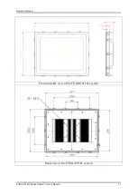
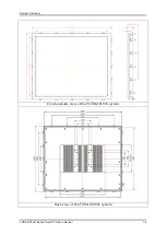
Page 9: ...System Overview FUDA2 S1x21 Series Panel PC User s Manual 1 5 1 4 Mechanical Dimension Front and side view of the FUDA2 S1021 system Back view of the FUDA2 S1021 system...

Page 10: ...System Overview FUDA2 S1x21 Series Panel PC User s Manual 1 6 Front and side view of the FUDA2 S1221 system Back view of the FUDA2 S1221 system...

Page 11: ...System Overview FUDA2 S1x21 Series Panel PC User s Manual 1 7 Front and side view of the FUDA2 S1521 system Back view of the FUDA2 S1521 system...

Page 12: ...System Overview FUDA2 S1x21 Series Panel PC User s Manual 1 8 Front and side view of the FUDA2 S1721 system Back view of the FUDA2 S1721 system...

Page 13: ...System Overview FUDA2 S1x21 Series Panel PC User s Manual 1 9 Front and side view of the FUDA2 S1921 system Back view of the FUDA2 S1921 system...

Page 14: ...ely disconnected from the DC main power source when the DC power cord is disconnected either from the power source or the unit Therefore the DC power cord and its connectors must always remain within...

Page 15: ...tatic Discharge ESD A sudden discharge of electrostatic electricity can damage electrostatic sensitive devices or circuits Adequate packaging and grounding techniques are essential to avoid damage Fol...

Page 16: ...vice pursuant to Part 15B of the FCC Rules These limits are designed to provide reasonable protection from harmful interference when the equipment is operated in a commercial environment This equipmen...

Page 17: ...that you can easily configure your system 2 1 Embedded Board H W Jumper Setting Introduction 2 1 1 Main Board FUDA2 S1x21 Series Panel PC adopts PEB 99A4 mother board You may configure the Panel PC by...

Page 18: ...0 Battery Connector J11 PCI E X4 Slot Right angle for Audio and COM Port Signal J12 USB Port 0 1 D Sub Connector Up USB2 0 Down USB3 0 J13 RJ45 Connector J14 RJ45 Connector J15 DVI I D sub Connector J...

Page 19: ...rce adjust pin SW1 LCD Resolution Setup SW2 AT ATX BIOS recovery Setup J8 GPIO Connector 2 5 Pin Header 2mm PIN NO DESCRIPTION PIN NO DESCRIPTION 1 GPIO0 2 GPIO4 3 GPIO1 4 GPIO5 5 GPIO2 6 GPIO6 7 GPIO...

Page 20: ...D 2 LED Hi Orange LED Low Green LED 3 Power Button 4 Power Button 5 NC J21 Touch Panel Connector 1 6 Pin Header 2 54mm PIN NO DESCRIPTION 1 UL 2 UR 3 Probe 4 LL 5 LR J22 USB Port 3 Connector 1 5 Pin W...

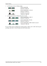
Page 21: ...TFT LCD JP4 LCD Panel Type Setup PIN NO DESCRIPTION 1 3 3 5 2 4 4 6 Short CCFL LCD Short LED LCD Default Short CCFL LCD Brightness Limit Short LED LCD Brightness Limit JP7 GPIO Power Selection PIN NO...

Page 22: ...tput JP13 COM3 Pin 9 Function Setup PIN NO DESCRIPTION 1 2 3 4 5 6 Short 5V Output Short RI Function Default Short 12V Output SW1 LCD Resolution Setup PIN NO Resolution Port 1 2 3 4 ON ON ON ON 800 x...

Page 23: ...anel size Note Diagram of adjusting to resolution 800 x 600 SW2 AT ATX BIOS recovery Setup PIN NO DESCRIPTION 1 4 Port1 ON AT Mode OFF ATX Mode Default 2 3 Port2 ON Recover BIOS OFF Disable Default No...

Page 24: ...422 485 mode setup Note Both COM1 COM2 support RS 232 422 485 selectable in BIOS menu RS 232 Mode Setup PIN No Signal Description PIN No Signal Description 1 Data Carrier Detect DCD 2 Receive Data RX...

Page 25: ...s Manual 2 9 RS 422 Mode Setup PIN No Signal Description PIN No Signal Description 1 TX 2 TX 3 Rx 4 Rx 5 GND 6 RTS 7 RTS 8 CTS 9 CTS RS 485 Mode Setup PIN No Signal Description PIN No Signal Descripti...

Page 26: ...Panel PC allows users to select different I O combinations for various market demands Note For FUDA2 S1021 there re three I O options including 2x RS 232 422 485 or 1x Line out and 1x RS 232 422 485...

Page 27: ...Memory module to the slot 4 Press down the memory module and finish installation 2 4 HDD Installation FUDA2 Series supports 1x 2 5 HDD SSD The unique design of the HDD tray allows easy installation a...

Page 28: ...used as an example to demonstrate installation process below 1 Unscrew the back cover to detach it 2 Remove the IPC back cover 3 Connect SMA cable to module 4 Insert the card to mini PCIe socket onbo...

Page 29: ...ing Started FUDA2 Series support 12 24V DC 20 input via 3 pin terminal block connector Minimum 22 AWG 90 C wiring conductor for power connection 1 Male type 3 pin terminal block connector located at r...

Page 30: ...rs don t need to install touch screen driver for projected capacitive multi touch because driver is included in operating system Do not use a hard or a pointed object like screw drivers or pliers to o...

Page 31: ...LED HDD LED Off N A N A Working Green Red Gigabit Ethernet Two Gigabit Ethernet 10 100 1000 Mbits sec LAN ports by using dual Intel I210IT GbE Ethernet Controller Support Jumbo Frame USB Universal Se...

Page 32: ...FUDA2 S1221 FUDA2 S1521 FUDA2 S1721 FUDA2 S1921 Default 0 N A Option 0 2 2x RS 232 422 485 Option 1 3 2x RS 232 422 485 1x RS 232 Option 2 1 1x RS 232 422 485 Line out Connectors for audio line out Mo...

Page 33: ...unt holes and kits Check the wall thickness cut out dimension and installation guide below Note These mounting clips have to be removed at first in order to install the system into a sub frame or a pa...

Page 34: ...system on a non textured surface in order to ensure front sealing against dust and water Verify the perfect condition of the seal at the rear of the front plate The seal has to be in place without inj...

Page 35: ...Manual 2 19 Installation Guide 1 Separate the VESA plate from the wall plate 2 Fix the wall plate to desired mounting position on the wall 3 Attach the unit to VESA plate using M4 10L screws 4 Slide...

Page 36: ...l drivers are included in Panel PC Series CD title in the accessory box 3 2 Windows 7 Gesture for Multi Touch Demand Windows Touch Pack for windows 7 For multi touch application please download Window...

Page 37: ...tic program will prompt the user to enter the SETUP program Some errors are significant enough to abort the start up 4 1 Entering Setup Launch System Setup Power on the computer and the system will st...

Page 38: ...gurations such as time date etc BIOS Information Memory Information These items show the firmware and memory specifications of your system Read only System Date The date format is Day Month Date Year...

Page 39: ...BIOS Setup Information FUDA2 S1x21 Series Panel PC User s Manual 4 3 4 3 Configuration Use this menu to set up the items of special enhanced features...

Page 40: ...cores to enable in each processor package The choice All Default 1 Intel Virtualization Cores When enabled a VMM can utilize the additional hardware capabilities provided by Vander pool Technology Th...

Page 41: ...ipset feature High Precision Timer Enable or Disable the High Precision Event Timer The choice Disabled Enabled Default Audio Controller Control Detection of the Azalia device Disabled Azalia will be...

Page 42: ...acy PXE Rom Disable Not Launch Rom Enabled Force Launch Rom The choice Disabled Default Enabled LAN Controller 2 Enable or Disable LAN Controller 2 PCI Express Port 3 The choice Disabled Enabled Defau...

Page 43: ...able IGD Turbo Enable Enable IGD Turbo Enable Disable IGD Turbo Disable Choices Enable Default Disable Primary Display Select which of IGD PCI Graphics device should be Primary Display Choices Auto IG...

Page 44: ...vated during POST This as no effect if external graphics present Secondary will appear based on your Selection VGA modes will be supported only on primary display Choices VBIOS Default Default DVI LVD...

Page 45: ...BIOS Setup Information FUDA2 S1x21 Series Panel PC User s Manual 4 9 PCI PCIE Configuration PCI PCI X and PCI Express Setting...

Page 46: ...the Chipset Choices Enable Default Disable Speed Configuration PCIe Speed Choices Auto Default Gen1 Gen2 PCI Express Configuration Port 1 Enable or Disable the PCI Express Port 1 in the Chipset Choic...

Page 47: ...Manual 4 11 Speed Configuration PCIe Speed Choices Auto Default Gen1 Gen2 PCI Express Configuration Port 3 Enable or Disable the PCI Express Port 3 in the Chipset Choices Enable Default Disable Speed...

Page 48: ...ns setting Serial ATA SATA Enable or Disable Serial ATA Choices Disabled Enabled Default SATA Mode Select IDE AHCI Choices Disabled IDE AHCI Default CF Device Enabled Disabled CF Device Choices Disabl...

Page 49: ...or EFI applications Choices Enabled Disabled Default XHCI Legacy Support Enable Disable XHCI Controller Legacy support Choices Enabled Disabled Default XHCI Hand off This is a workaround for OSes with...

Page 50: ...ings XHCI Mode Mode of operation of XHCI controller Choices Smart Auto Default Auto Enable Disable USB2 Link Power Management Enable Disable USB2 Link Power Management Choices Enable Default Disable U...

Page 51: ...e USB Port 1 USB 2 0 port on Board Choices Enable Default Disable USB Port 2 Enable Disable USB Port 2 The USB port turn into a mini PCIE Choices Enable Default Disable USB Port 3 Enable Disable USB P...

Page 52: ...t the highest ACPI sleep state the system will enter when the SUSPEND button is pressed Choices Suspend Disable S3 Suspend to RAM Default Restore AC Ring Loss Select AC Power state when power is re ap...

Page 53: ...ace Set Current UART mode RS232 RS485 RS485 RS422 Choices RS232 Default RS485 HALF DUFLEX RS485 422 FULL DUFLEX Termination Control Set Termination Control Disabled Enabled Choices Disabled Enabled De...

Page 54: ...as Transceiver else Disabled as Receiver Choices Disabled Default Enabled Serial Port Enable or Disable Serial Port COM IO 240H IRQ 10 Choices Disabled Enabled Default Serial Port Enable or Disable Se...

Page 55: ...BIOS Setup Information FUDA2 S1x21 Series Panel PC User s Manual 4 19 Hardware Monitor Monitor hardware status...

Page 56: ...Manual 4 20 4 4 Security Password Check Mode Setup check password when enter setup screen Power On check password on every time system power on Choices Setup Default Power On Administrator Password S...

Page 57: ...Number of seconds to wait for setup activation key 65535 0xFFFF means indefinite waiting Choices Default 5 Bootup NumLock state Select the keyboard NumLock state Choices On Default Off Post Report Pos...

Page 58: ...Option ROM IMMEDIATE execute the trap right away POSTPONED execute the trap during legacy boot Choices Immediate Default Postponed Storage Controls the of execution of UEFI and Legacy Storage OpROM Ch...

Page 59: ...mation FUDA2 S1x21 Series Panel PC User s Manual 4 23 4 6 Save and Exit Save Changes and Reset Reset the system after saving the changes Pressing Enter on this item asks for confirmation Save configur...

Page 60: ...Changes and Exit Reset system setup without saving any changes Pressing Enter on this item asks for confirmation Reset without saving Restore Defaults Restore Load Default values for all the setup opt...

Page 61: ...ide by the safety instructions 5 3 Liability Limitations Exemption from the Warranty Obligation In the event of damage to the system unit caused by failure to abide by the hints in this manual and on...

Page 62: ...idity or alkalinity which could react with the paint or printed color or plastic should be avoided Q2 How to set OS Selection for different OS Answer You can find OS Selection under BIOS setting Step1...

Page 63: ...r CMOS Setup Q4 How to set AT mode for the system Answer The default setting is ATX mode user needs to press the power button in order to turn on the system By adjusting SW2 port 1 jumper on board and...

Page 64: ...Panel PC and press the power button to power on Step3 Press Del key during the POST Power On Self Test process will enter BIOS setup screen Step4 Boot to EFI Shell mode by choosing below item Step5 Ty...

Page 65: ...ser s Manual 6 4 Step5 Type fs3 command to switch to the root of the USB pen drive And type dir to find the directory of fs3 Step6 Type the update command to start flash BIOS processes Step7 Press Ctr...

Reviews: