background image

System Installation 

FUDA3-S1x22 Series Panel PC User’s Manual 

2-2 

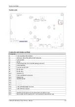
Solder side: 


Connector and Jumper setting: 

Connector 
J1 

Full-size Mini-PCIe Socket 

J2 

Half-size Mini-PCIe/Mini-mSATA Socket  

J3 

SATA+PWR 

J4 

GPIO 

J5 

LPC Debug Port (For Port 80 debug card use) 

J6 

CMOS Battery 

J7 

Customize I/O Slot 

J8 

RJ-45 Port 

J9 

RJ-45 Port  

J10 

USB 3.0 *2 

J11 

Terminal Block Connector 

J12 

HDMI Port 

J13 

USB OTG Port 

J15  

Front Panel 

J16 

Speaker 

J17 

Speaker 

J18 

LCD LVDS Backlight Control 

J19 

LCD LVDS Connector 

J21 

Microphone Header 

J22 

USB 2.0 Connector (For Touch board connection use ) 

J23 

Micro SIM Card Socket (for J1 Full-size Mini-PCIe socket use) 

Summary of Contents for FUDA3-S1-22 Series

Page 1: ...d Fan less Projective Capacitive Touch Panel PC Powered by Intel Atom x7 E3950 Quad core Processor User s Manual Version 1 0 Copyright Portwell Inc 2016 All rights reserved All other brand names are r...

Page 2: ...ounting Method 2 20 2 9 1 Panel Mount 2 20 2 9 2 VESA Mount 2 22 Chapter 3 Driver Installation Touch Usage and PET introduction 3 1 3 1 How to Get the Driver 3 1 3 2 Driver Installation 3 2 3 2 1 Inte...

Page 3: ...advanced BIOS performance and update new BIOS In addition POST checkpoint list will give users some guidelines of trouble shooting Chapter 5 Important Instructions Indicate some instructions which mu...

Page 4: ...Preface Revision History Revision Date Details of Change s V1 0 2022 6 20 Initial Release...

Page 5: ...anel PC Series is responsive even when thick industrial gloves are worn and supports palm rejection Moisture contaminant and cutting oil are common in an industrial environment so it is important thes...

Page 6: ...UDA3 Series Panel PC features all required interfaces for industrial application 12V 24V DC input dual LAN multiple USB ports and RS 232 422 485 selectable in BIOS with auto flow function Different I...

Page 7: ...3 S1522 Screws for HDD installation M3X4L Screw 4 pieces 3 pin Terminal Block Connector Female Optional Panel Mount Kits Panel Size Kits pcs 10 4 8 pieces 12 1 8 pieces 15 14 pieces 17 16 pieces 19 20...

Page 8: ...tension Kit for FUDA3 S1222 1522 2x RS 232 422 485 2x USB 2 0 Expansion Option 0 2x RS 232 422 485 1x RS 232 Expansion Option 1 If any of these items is damaged or missing please contact your vendor a...

Page 9: ...1 x SMA Antenna hole for WiFi 3G Solution Expansion 1 x Full size Mini PCIe socket 1 x Full size Mini PCIe socket 1 x Half size Mini PCIe Mini mSATA socket switch by jumper 2 x RS 232 422 485 1 x RS 2...

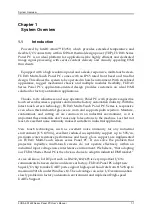
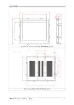
Page 10: ...System Overview FUDA3 S1x22 Series Panel PC User s Manual 1 6 1 4 Mechanical Dimension Front and side view of the FUDA3 S1022 system Back view of the FUDA3 S1022 system...

Page 11: ...System Overview FUDA3 S1x22 Series Panel PC User s Manual 1 7 Front and side view of the FUDA3 S1222 system Back view of the FUDA3 S1222 system...

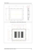
Page 12: ...System Overview FUDA3 S1x22 Series Panel PC User s Manual 1 8 Front and side view of the FUDA3 S1522 system...

Page 13: ...ely disconnected from the DC main power source when the DC power cord is disconnected either from the power source or the unit Therefore the DC power cord and its connectors must always remain within...

Page 14: ...tatic Discharge ESD A sudden discharge of electrostatic electricity can damage electrostatic sensitive devices or circuits Adequate packaging and grounding techniques are essential to avoid damage Fol...

Page 15: ...vice pursuant to Part 15B of the FCC Rules These limits are designed to provide reasonable protection from harmful interference when the equipment is operated in a commercial environment This equipmen...

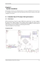
Page 16: ...that you can easily configure your system 2 1 Embedded Board H W Jumper Setting Introduction 2 1 1 Main Board FUDA3 S1x22 Series Panel PC adopts PEB 99A5 mother board You may configure the Panel PC by...

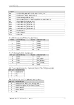
Page 17: ...C Debug Port For Port 80 debug card use J6 CMOS Battery J7 Customize I O Slot J8 RJ 45 Port J9 RJ 45 Port J10 USB 3 0 2 J11 Terminal Block Connector J12 HDMI Port J13 USB OTG Port J15 Front Panel J16...

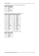
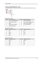
Page 18: ...set Button SW2 Power Button D29 State LED J4 GPIO Connector 2 5 Pin Header 2mm PIN NO DESCRIPTION PIN NO DESCRIPTION 1 GPIO1 2 GPIO5 3 GPIO2 4 GPIO6 5 GPIO3 6 GPIO7 7 GPIO4 8 GPIO8 9 GND 10 5V J5 LPC...

Page 19: ...nnector 2 15 Pin Hirose 1 25mm PIN NO Description PIN NO Description 1 YAP0 2 YAM0 3 YAP1 4 YAM1 5 YAP2 6 YAM2 7 YAP3 8 YAM3 9 CLKAP 10 CLKAM 11 YBP0 12 YBM0 13 YBP1 14 YBM1 15 YBP2 16 YBM2 17 YBP3 18...

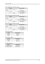
Page 20: ...12V Low Active JP2 Panel Voltage Setup PIN NO DESCRIPTION 1 3 3 5 3 4 Voltage Short 3 3V TFT LCD Default Short 5V TFT LCD 12V TFT LCD JP3 CMOS Setup PIN NO DESCRIPTION 1 2 Normal Keep CMOS Setup Defau...

Page 21: ...N NO DESCRIPTION 1 2 3 4 5 6 Short 5V Output Short RI Function Default Short 12V Output JPB2 COM4 Pin 9 Function Setup PIN NO DESCRIPTION 1 2 3 4 5 6 Short 5V Output Short RI Function Default Short 12...

Page 22: ...2 7 2 1 2 Extension Board FUDA3 S1x22 Series Panel PC can adopt different I O extension board You may configure the Panel PC by different I O kit options to match market needs PA P1S2 for FUDA3 S1022...

Page 23: ...cription 1 Data Carrier Detect DCD 2 Receive Data RXD 3 Transmit Data TXD 4 Data Terminal Ready DTR 5 GND 6 Data Set Ready DSR 7 Request to Send RTS 8 Clear to Send CTS 9 Ring Indicator RI RS 422 Mode...

Page 24: ...rther enhance system flexibility as well as to increase the versatility in application fields FUDA3 S1x22 Series Panel PC allows users to select different I O combinations for various market demands N...

Page 25: ...you don t choose any I O expansion kit on ATO order 2 Confirm which kinds of I O expansion kit will be installed on which PPC model 3 Unscrew 2 handle screws and M3x4 screw by screw driver to take out...

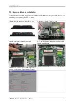
Page 26: ...one DDR3L SO DIMM memory module It s easy to install by just opening the back cover 1 Unscrew the back cover to detach it 2 Remove the IPC back cover 3 Insert Memory module into the Memory socket 4 P...

Page 27: ...tion and maintenance Note The height of Hard Disk or Solid State Drive must be less than 10mm 1 Loose HDD cover bracket and then remove it 2 Push the rod to release HDD tray 3 Install the HDD or SSD i...

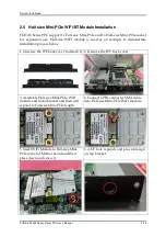
Page 28: ...ample to demonstrate installation process below 1 Unscrew the IPC back cover to detach it 2 Remove the IPC back cover 3 Assemble Half size Mini PCIe WiFi module and metal bracket and then will expand...

Page 29: ...anual 2 14 7 Please poke screw driver into the ANT hole until real hole is appeared 8 Screw the SMA cable to ANT hole at top bracket 9 Arrange the SMA cable inside 10 Screw IPC back cover and finish t...

Page 30: ...t on Pin1 2 Note JP4 is jumper switch between Mini PCIe and Mini mSATA signal Default setting Pin1 2 is for Mini mSATA 1 Unscrew the IPC back cover to detach it 2 Remove the IPC back cover 3 J2 is Hal...

Page 31: ...ock connector in accessory kit 3 Plug DC source cable into 3 pin terminal block connector and then fix it by screw driver 4 Plug 3 pin thermal block cable into power input connector of system and then...

Page 32: ...well Users don t need to install touch screen driver for projected capacitive multi touch because driver is included in operating system Do not use a hard or a pointed object like screw drivers or pl...

Page 33: ...r LED and HDD LED It demonstrates the power in and HDD working status of the Panel PC Status Power LED HDD LED Off N A N A Working Green Red Gigabit Ethernet Two Gigabit Ethernet 10 100 1000 Mbits sec...

Page 34: ...S 232 422 485 connection Note The RS 232 422 485 configuration is determined by BIOS setting Check BIOS setting for details Model With different I O kit combination Total of COM ports Details FUDA3 S1...

Page 35: ...Note Refer to section 2 5 for installation guide 2 9 Mounting Method 2 9 1 Panel Mount The Panel PC can be mounted into a panel or a sub frame for industrial cabinet via panel mount holes and kits Che...

Page 36: ...N A N A N A N A N A N A N A N A N A Installation Guide 1 Hook Clip 2 Screw the Clip tightly Torque Value 8kg 3 Hook the mounting clamps with screws included from the back side Mount the system on a no...

Page 37: ...e in order to be mounted on a wall M4 10L screws must be used to fix the system onto the wall mount adapter plate Installation Guide 1 Separate the VESA plate from the wall plate 2 Fix the wall plate...

Page 38: ...allation Touch Usage and PET introduction 3 1 How to Get the Driver All drivers of FUDA3 Series Panel PC are provided at download center of Portwell web site https www portwell com tw support center d...

Page 39: ...or It s a new chipset that some old operating systems might not be able to recognize To overcome this compatibility issue for Windows Operating Systems such as Windows 10 please install its INF before...

Page 40: ...Graphics 505 Processor Graphics indicates graphics processing circuitry integrated into the processor providing the graphics compute media and display capabilities Intel HD Graphics Iris Graphics Iri...

Page 41: ...User s Manual 3 4 4 Intel Graphic Driver Installer 5 Please right bar until it appears Agree to Click it 6 Click Start 7 Click Install 8 Installation Complete and click Option reboot or Finish 9 Check...

Page 42: ...river Installation Please kindly find Intel I210 Ethernet driver at Portwell download center It supports Windows 10 Operating System 1 Click Autorun file and double click to execute it 2 Appear Intel...

Page 43: ...PC User s Manual 3 6 5 Choose I accept the term in the license agreement and click Next 6 Click Next 7 Click Install 8 Install Process 9 Install wizard Completed and click Finish 10 Check Intel I210 N...

Page 44: ...ine driver at Portwell download center It supports Windows 10 Operating System 1 Select SetupTXE file and double click to execute it 2 Appear Intel Trust Execution Engine screen and then click Next 3...

Page 45: ...Software Instructions FUDA3 S1x22 Series Panel PC User s Manual 3 8 5 Click Next 6 Install Process 7 Click Finish Check Intel Trust Execution Engine Interface is detected by Device Manger...

Page 46: ...ver Ethernet driver at Portwell download center It supports Windows 10 Operating System 1 Click SetupSerialIO file and double click to execute it 2 Appear Intel Serial IO and then click Next 3 Appear...

Page 47: ...A3 S1x22 Series Panel PC User s Manual 3 10 5 Click Next 6 Click Next 7 Click Next 8 Install Process 9 Intel Serial IO Completion and click Finish 11 Check Intel Trust Execution Engine Interface is de...

Page 48: ...The advantage can solve I O communication slowly problem in factory automation environment After installing Nuvoton Super I O driver please kindly check if the driver is installation successfully on...

Page 49: ...Software Instructions FUDA3 S1x22 Series Panel PC User s Manual 3 12 5 Check Nuvoton COM port devices are detected by Device Manager of Windows 10...

Page 50: ...Fi module and Bluetooth driver of B4729070 ZQ802XRACB2 AJ that built in Realtek 8812AE and Bluetooth chipset under Windows 10 for demonstration Install WiFi driver 1 Click Setup file and double click...

Page 51: ...reless icon and it will show all of AP near to your side then choose one of AP with network security key you know 6 When AP is connected with network security key it will show Connected secured 7 Open...

Page 52: ...UDA3 S1x22 Series Panel PC User s Manual 3 15 Install Bluetooth driver 1 Select BT driver directory 2 Click Setup file and double click to execute it 3 Appear Preparing setup screen 4 Appear Realtek B...

Page 53: ...now installing Realtek Bluetooth screen 7 Appear InstallShield Wizard Complete screen and click Finish to restart the computer 8 Click Realtek Bluetooth 4 0 Adapter device is detected by Device Manage...

Page 54: ...der Windows 10 How to test 10 points touch support working properly under Windows 10 1 Check Projective Capacitive Touch device is detected by Device Manager of Windows 10 2 Execute Paint program and...

Page 55: ...more information and documentation Portwell EC Auto Test Tool PECAT The Portwell EC Auto Test Tool PECAT is a brand new utility which innovated by Portwell PECAT now is available for Portwell s custom...

Page 56: ...information such as Platform name API Library version BIOS vendor and BIOS version 6 Show Watch Dog Timer Function and how to set the parameter 7 Show Hardware Monitor information such as Temperature...

Page 57: ...tic program will prompt the user to enter the SETUP program Some errors are significant enough to abort the start up 4 1 Entering Setup Launch System Setup Power on the computer and the system will st...

Page 58: ...gurations such as time date etc BIOS Information Memory Information These items show the firmware and memory specifications of your system Read only System Date The date format is Day Month Date Year...

Page 59: ...BIOS Setup Information FUDA3 S1x22 Series Panel PC User s Manual 4 3 4 3 Configuration Use this menu to set up the items of special enhanced features...

Page 60: ...package The choice Disabled Default Enabled Intel Virtualization Cores When enabled a VMM can utilize the additional hardware capabilities provided by Vander pool Technology The choice Disabled Enable...

Page 61: ...IOS Setup Information FUDA3 S1x22 Series Panel PC User s Manual 4 5 Turbo Mode Turbo Mode The choice Disabled Enabled Default C States Enable or disable CPU C states The choice Disabled Default Enable...

Page 62: ...er s Manual 4 6 Chipset Configuration Configuration Chipset feature HD Audio Support Enable or Disable HD Audio Support The choice Disabled Enabled Default 8254 Clock Gating Enable or Disable 8254 Clo...

Page 63: ...choice Disabled Enabled Default LAN Controller 2 Intel Ethernet Controller WGI210AT LAN MAC address 00 90 FB xx xx xx Enable or Disable LAN Controller 2 PCI Express Port 4 The choice Disabled Enabled...

Page 64: ...isplay control GOP GOP Driver Enable GOP Driver will unload VBIOS Disable it will load VBIOS Choices Enable Default Disable GOP Brightness Level Setup Panel Brightness under BIOS and it will affect Br...

Page 65: ...ill appear based on your Selection VGA modes will be supported only on primary display Choices Auto Default eDP to LVDS Configuration Panel Profile Select Panel Profile for current Choices 1024x768 De...

Page 66: ...l Clock Mode Select Clock output for LVDS Choices Both Default Even Bus Odd Bus OEM Profile Allow User to define new Panel according to property of Panel and Save on BIOS Panel 1 Configuration Profile...

Page 67: ...Choices 2500 Default H Active Pixels H Active Pixels Pixel Choices 640 Default H Blank Pixels H Blank Pixels Pixel Choices 160 Default H Offset Pixels H Offset Pixels Pixel Choices 16 Default H Width...

Page 68: ...olarity is Positive 0x18 Signal Polarity is Non Positive Choices Positive Default Non Positive PCI PCIE Configuration PCI Express Root 5 Enable or disable PCI Express Root 5 function Choices Enabled D...

Page 69: ...pported per port Choices Disabled Enabled Default SATA Speed Selection Select SATA interface speed Choices Auto Default Gen1 Gen2 Gen3 SATA Port 0 Port 0 Enable or Disable SATA Port 0 Choices Disabled...

Page 70: ...or Disable SATA Port 1 Choices Disabled Enabled Default Port 0 Hot Plug Capability If enable SATA port will be reported as hot Plug capable Choices Disabled Default Enabled SATA Device Type Identify t...

Page 71: ...USB Devices 1x Drive 1 Keyboard 1 Mouse 1 Point SOC USB Configuration USB Port 1 Enable Disable USB Port 1 Choices Enable Default Disable USB Port 2 Enable Disable USB Port 2 Choices Enable Default Di...

Page 72: ...bled Default Disabled USB Mass storage Driver Support Enable Disable USB Mass storage Driver Support Choices Enabled Default Disabled USB hardware delays and time outs USB transfer time out The time o...

Page 73: ...some OS Choices Disabled Enabled Default ACPI Sleep State Select the highest ACPI sleep state the system will enter when the SUSPEND button is pressed Choices Suspend Disable S3 Suspend to RAM Default...

Page 74: ...IO Chip Parameters Serial Port 1 Configuration Serial Port Enable or Disable Serial Port 1 COM 1 Choices Disabled Enabled Default Device Setting Assign Serial Port COM 1 IO 3F8H IRQ 4 UART Mode Set C...

Page 75: ...ort 2 Configuration Serial Port Enable or Disable Serial Port 2 COM 2 Choices Disabled Enabled Default Device Setting Assign Serial Port COM 2 IO 2F8H IRQ 3 UART Mode Set Current UART Mode RS232 RS485...

Page 76: ...ort 3 Configuration Serial Port Enable or Disable Serial Port 3 COM 3 Choices Disabled Enabled Default Device Setting Assign Serial Port COM 3 IO 240H IRQ 10 UART Mode Set Current UART Mode RS232 RS48...

Page 77: ...Disable Serial Port 4 COM 4 Choices Disabled Enabled Default Device Setting Assign Serial Port COM 4 IO 248H IRQ 11 UART Mode Set Current UART Mode RS232 RS485 RS422 Choices RS232 Default RS485 RS422...

Page 78: ...BIOS Setup Information FUDA3 S1x22 Series Panel PC User s Manual 4 22 Hardware Monitor Monitor hardware status...

Page 79: ...BIOS Setup Information FUDA3 S1x22 Series Panel PC User s Manual 4 23 Serial Port Console Redirection COM0 Console Redirection Console Redirection Enable or Disable Choices Disabled Default Enabled...

Page 80: ...nction keys etc VT UTF8 Uses UTF8 encoding to map Unicode chars onto 1 or more bytes Choices ANSI Default VT100 VT100 VT UTF8 Bits per second Emulation ANSI Extended ASCII char set VT100 ASCII char se...

Page 81: ...quire more than 1 stop bit Choices 1 Default 2 Flow Control Flow control can prevent data loss from buffer overflow When sending data if the receiving buffers are full a stop signal can be sent to sto...

Page 82: ...s Manual 4 26 Intel R I210 Gigabit Network Connection Configure Gigabit Ethernet device parameters NIC Configuration Click to configure the network deice port Blink LEDs Identify the physical network...

Page 83: ...iguration Link Speed Specifies the port speed used for the selected boot protocol Choices Auto Negotiated Default 10 Mbps Half 10 Mbps Full 100 Mbps Half 100 Mbps Full Wake on LAN Enabled the server t...

Page 84: ...s Manual 4 28 Intel R I210 Gigabit Network Connection Configure Gigabit Ethernet device parameters NIC Configuration Click to configure the network deice port Blink LEDs Identify the physical network...

Page 85: ...iguration Link Speed Specifies the port speed used for the selected boot protocol Choices Auto Negotiated Default 10 Mbps Half 10 Mbps Full 100 Mbps Half 100 Mbps Full Wake on LAN Enabled the server t...

Page 86: ...assword Description Password Check Mode Setup check password when enter setup screen Power On check password on every time system power on Choices Setup Default Power On Setup Administrator Password S...

Page 87: ...eout Number of seconds to wait for setup activation key 65535 0Xffff means indefinite waiting Choices 2 Default 1 65535 Bootup NumLock State Select the Keyboard NumLock State Choices On Default Off Po...

Page 88: ...r Disables Quiet Boot option and Full screen Logo Choices Disabled Default Enabled Boot Mode Select Select Boot mode LEGACY UEFI Choices UEFI Default Legacy FIXED BOOT ORDER Priorities Boot Option 1 S...

Page 89: ...BIOS Setup Information FUDA3 S1x22 Series Panel PC User s Manual 4 33 UEFI Hard Disk Drive BBS Priorities UEFI USB Drive BBS Priorities...

Page 90: ...mation FUDA3 S1x22 Series Panel PC User s Manual 4 34 4 6 Save and Exit Save Changes and Reset Reset the system after saving the changes Pressing Enter on this item asks for confirmation Save configur...

Page 91: ...ks for confirmation Reset without saving Default Option Restore Defaults Restore Load Default values for all the setup options Boot Override UEFI Built in EFI Shell Boot option filter UEFI only Reset...

Page 92: ...age to the system unit caused by failure to abide by the hints in this manual and on the unit especially the safety instructions Portwell Inc shall not be required to respect the warranty even during...

Page 93: ...d oil Q2 What supposed to do when forget the password of system BIOS Answer Please turn off the power supply and then find the JP1 to set it from 1 2 short to 2 3 short Wait for 5 seconds to clean pas...

Page 94: ...te efi and Readme txt two files Step2 Insert your USB pen drive in USB port of the FUDA3 Series Panel PC and press the power button to power on Step3 Press Del key during the POST Power On Self Test p...

Page 95: ...ser s Manual 6 4 Step6 Type fs3 command to switch to the root of the USB pen drive And type dir to find the directory of fs3 Step7 Type the update command to start flash BIOS processes Step8 Press Ctr...

Page 96: ...ges and Exit After changes Panel brightness will be enhanced and brighter But remember FUDA3 series adopt Industrial LED type Panel support 50 000 hours MTBF for LED light bar so when the brightness i...

Page 97: ...Frequent Asked Questions FUDA3 S1x22 Series Panel PC User s Manual 6 6...

Page 98: ...Questions FUDA3 S1x22 Series Panel PC User s Manual 6 7 Adjust Display Brightness under Windows 10 Select This PC and click right key of mouse and then click Display setting Change Display Brightness...

Page 99: ...Frequent Asked Questions FUDA3 S1x22 Series Panel PC User s Manual 6 8...

Reviews: