background image

NAR-4040  User’s Manual


36

 
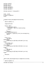
          lea dx,PROMP_2_CR_LF 
          mov ah,09h 
          int 21h 
 
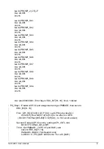
          lea dx,PROMP_Str1 
          mov ah,09h 
          int 21h 
          lea dx,PROMP_Str2 
          mov ah,09h 
          int 21h 
          lea dx,PROMP_Str3 
          mov ah,09h 
          int 21h 
          lea dx,PROMP_Str4 
          mov ah,09h 
          int 21h 
          lea dx,PROMP_Str5 
          mov ah,09h 
          int 21h 
          lea dx,PROMP_Str6 
          mov ah,09h 
          int 21h 
          lea dx,PROMP_Str7 
          mov ah,09h 
          int 21h 
          lea dx,PROMP_Str8 
          mov ah,09h 
          int 21h 
          lea dx,PROMP_Str9 
          mov ah,09h 
          int 21h 
          lea dx,PROMP_StrA 
          mov ah,09h 
          int 21h 


          mov edx,00000000h ; Error flag in EDX_BIT[16..18], 0=ok, 1=failed 
 
;  PG_Step1 : Enable ACPI IO port assignment and get PMBASE, then save to 
;             EBX_Bit[31..16] 

;             First : GPI_ROUT bit[13,12] P [0,0] : Let GPI6 not evoke SCI. 
;                     Write GPI_Rout bit[13,12] to [0,0] for no effect on GPI6 
;               ( B0:D31:F0:Offset_B8h-Bit[13,12]P[0,0] , no SCI event evoked) 

;             Second: Enabe ACPI IO port by  setting ACPI_CNTL bit4 
;                     B0:D31:F0:Offset_44h_bit4P1 
;             Third : Get PMBASE  ( ACPI I/O port BAR ) and 
;                     save to EBX_bit[31..16]. 
;                     PMBASE=:B0:D31:F0:Offset[40..43h] 
;                     Let Bit0 = 0.( PCI_BAR bit0 returns 1 for a IO_BAR ) 

Summary of Contents for NAR-4040

Page 1: ...ns Appliance User s Manual Revision 010 Portwell Inc 3F No 92 Nei Hu Rd Sec 1 Taipei 114 Taiwan R O C Headquarter 886 2 2799 2020 Fax 886 2 2799 1010 http www portwell com tw Email info mail portwell com tw ITEM NO B8980650 ...

Page 2: ...ng a Different Processor 11 2 10 PCI Card Install Remove 13 2 11 Assembling the System 14 2 12 Configuring the System Board 15 2 13 Installing Memory 20 2 14 Using a Client Computer 21 Chapter 3 Operation Guides 24 3 1 Brief Guide for PPAP 3711VL 24 Chapter 4 Appendix 27 4 1 GPIO Sample code 27 4 2 Watch Dog Timer Sample code 31 4 3 Reset To Default Sample code 33 Chapter 5 EZIO 100 46 5 1 About E...

Page 3: ...NAR 4040 User s Manual 2 5 9 Sample Code 53 ...

Page 4: ... addressing a basic concept and operation of this whole system Chapter 1 Introduction It briefly talks about how this documentation is about Some guidelines for users who do not want to read through all the pages but still finding what they need Chapter 2 Hardware Configuration Setting and Installation This chapter shows how the hardware was put together Detail information is also included in this...

Page 5: ...find helpful tips or related information on Portwell s Web site http www portwell com tw A direct contact to Portwell s technical person is also available For further support Users may also contact our headquarter in Taipei or contact Portwell s distributors ...

Page 6: ...appliance system board and peripherals back into the antistatic bag when they are not in use or not installed in the chassis Some circuitry on the system board can continue to operate even though the power is switched off Under no circumstances should the Lithium coin cell that is being used to power the real time clock be allowed to be shorted The coin cell can heat under these conditions and pre...

Page 7: ...ssis and fits in all standard rack or cabinet Fig 2 1 Fig 2 2 Front accessible panel there are an EZIO a LED panel and a set of LAN ports The LAN ports number can be different according to model Fig 2 1 Front View of the Chassis Fig 2 2 Rear View of the Chassis NAR 4040 User s Manual 6 ...

Page 8: ...l 7 Fig 2 3 Remove the screw on the arrow tip of top cover Fig 2 4 Remove the screw on the arrow tip of the ear mount Fig 2 5 Push the top cover on both left and right upper side at the same time Fig 2 6 Slide lightly the top cover to rear side until it is stopped and then raise it up ...

Page 9: ... HDD is not pre installed you can install by yourself You need the parts from the accessory bag as shown on Figure 2 7 They are one HDD bracket several screws and one 44pin IDE cable from left to right Fig 2 8 Fix the hard disk drive on the HDD bracket with four sink head screws Fig 2 9 Plug the IDE cable into hard disk drive connector ...

Page 10: ...cket Fig 2 12 Fix the half assembled HDD with the four round head screws Fig 2 13 Complete 2 6 Installing a CF Compact Flash Card 1 To install a compact flash card it needs only to insert the CF card into the white socket on the adaptor board Fig 2 14 Fig 2 15 NAR 4040 User s Manual 9 ...

Page 11: ...ese steps 1 Pull out the lock arms on both side and the RAM module springs up automatically Fig 2 22 2 Press down gently on both left and right edges of the module Fig 2 23 until it clicks 3 Then reappear step 1 to 2 to install more RAM module Fig 2 25 Fig 2 22 Fig 2 23 NAR 4040 User s Manual 10 ...

Page 12: ... 2 24 2 The battery springs automatically Fig 2 25 4 Replace a new one and press it back with fingertip 2 9 Installing a Different Processor Installing CPU 1 Lift the handling lever of CPU socket outwards and upwards to the other end 2 Align the processor pins with holes on the socket Make sure that the notched corner or NAR 4040 User s Manual 11 ...

Page 13: ... CPU speed and voltage type to adjust the jumper settings properly Removing CPU 1 Unlock the cooling fan first 2 Lift the lever of CPU socket outwards and upwards to the other end 3 Carefully lift up the existing CPU to remove it from the socket 4 Follow the steps of installing a CPU to change to another one or place handling bar to close the opened socket 2 11 1 Configuring Processor Speed The sy...

Page 14: ...p to the system board as shown with red arrow Fig 2 30 assembling completion diagram 2 10 PCI Card Install Remove If the installation of PCI cards required please follow the instructions with care Fig 2 31 PCI Card secure base Fig 2 32 Install the secure base to the chassis NAR 4040 User s Manual 13 ...

Page 15: ...embling the System The mechanism of top cover assembly to chassis needs six screws to fix the top cover However by assembling the top cover there is one importance point the tongue of the cover must be inserted to the proper position so the six screw holes on the cover can match to the chassis Fig 2 36 Fig 2 37 NAR 4040 User s Manual 14 ...

Page 16: ... for optional LCD Key pad module Portwell Proprietary USB Interface Support two USB 2 0 ports for high speed I O peripheral devices Auxiliary I O Interfaces System reset switch Power LED LAN activity LED HDD LED interface Watchdog Timer 255 intervals from 0 5 min to 254 5 min by software programming Power Inlet One standard 20 pin ATX power connector One on board DC input jack PCI Golden Finger On...

Page 17: ... LAN5 LAN6 J6 J15 J24 J26 J27 J28 J29 J31 PW1 J40 J35 J34 J33 JP3 J30 JP2 J39 J37 DIMM1 DIMM2 J38 J32 J36 J19 J23 J4 J5 J8 J9 J16 JP1 J25 J10 J2 J3 J7 J11 J12 J13 J14 J20 J21 J22 J17 J18 19 20 9 10 5 10 5 10 13 26 2 4 2 2 2 4 4 5 6 10 2 2 4 9 2 10 7 10 39 40 43 44 Fig 2 38 PPAP 3711VL Jumper Locations 2 12 2 2 Connectors I O peripheral devices and Flash disk will be connected to these interface co...

Page 18: ...JP1 Secondary IDE Select Pin No Signal Description Shot Master NC Slave JP2 Clean CMOS Pin No Signal Description 1 2 Normal 2 3 Clean CMOS JP3 WDT Select Pin No Signal Description Shot WDT Reset NC WDT SMI J2 K B M S Pin No Signal Description 1 MDAT 2 3 GND 4 VCC 5 MCLK 6 KDAT 7 8 GND 9 VCC 10 KCLK J3 CRT Pin No Signal Description 1 RED 2 GREEN 3 BLUE 4 VSYNCR ...

Page 19: ...D5 5 DATA2 DATA4 6 DATA3 DATA5 7 GND2 GND4 8 DATA3 DATA5 9 GND2 GND4 10 VCC3 VCC5 J7 Parallel port Pin No Signal Description Pin No Signal Description 1 P_STB 2 P_PD0 3 P_PD1 4 P_PD2 5 P_PD3 6 P_PD4 7 P_PD5 8 P_PD6 9 P_PD7 10 ACK 11 BUSY 12 PE 13 SLCT 14 P_AFD 15 ERR 16 P_INIT 17 P_SLIN 18 GND 19 GND 20 GND 21 GND 22 GND 23 GND 24 GND 25 GND 26 N A J8 GPIO Pin No Signal Description Pin No Signal D...

Page 20: ...6_1000 2 L6_LINK LED 3 L6_100 4 L6_ACT J12 LAN5_LED Pin No Signal Description 1 L5_1000 2 L5_LINK LED 3 L5_100 4 L5_ACT J13 LAN4_LED Pin No Signal Description 1 L4_1000 2 L4_LINK LED 3 L4_100 4 L4_ACT J14 LAN3_LED Pin No Signal Description 1 L3_1000 2 L3_LINK LED 3 L3_100 4 L3_ACT J17 J30 Load_Default Pin No Signal Description 1 PRE 2 GND J18 RESET Pin No Signal Description ...

Page 21: ...J31 COM2 Pin No Signal Description 1 DCD 2 2 RXD 2 3 TXD 2 4 DTR 2 5 GND 6 DSR 2 7 RTS 2 8 CTS 2 9 RI 2 10 2 13 Installing Memory This PPAP 3711VL provides one 184 pin DDR socket The maximum memory size is 2GB Normally the DDR used could be 2 5V DDR with speed less than 70ns 7 you need to use DDR with speed less than 70ns 7 It is better to use PC2700 compliant memory chip on your system For system...

Page 22: ...pgrade your system performance except for getting technical information 2 14 Using a Client Computer 2 14 1 Connecting Using HyperTerminal If users use a headless NAR 4040 which should have no mouse keyboard and VGA output connected to it The console may be used to communicate with NAR 4040 If users would like to use console to access NAR 4040 using HyperTerminal will be one of many good choices I...

Page 23: ... the port settings to Baud rate 19200 Parity None Data bits 8 Stop bits 1 5 Turn on the power of raid after following screen was shown 6 You can then see the boot up information of NAR 4040 NAR 4040 User s Manual 22 ...

Page 24: ...7 This is the end of this section If the terminal did not port correctly please check the previous steps NAR 4040 User s Manual 23 ...

Page 25: ...igh performance 16C550 compatible UARTs to provide 16 byte send receive FIFOs Besides the two Universal Serial Bus ports provide high speed data communication between peripherals and PC The A built in Watch dog Timer function helps to monitor your system status The on board Flash ROM is used to make the BIOS update easier An AC DC adaptor power input jack is provided for AT mode operation The high...

Page 26: ...64 bit GTL based host bus interface optimized 64 bit DRAM interface without ECC to support two 2 5V DDR memory module at the maximum bus frequency of 533 MHz and 32 bit PCI bus interface to support on board PCI device The South Bridge 82810DB provides one channel dedicated Ultra DMA 100 IDE master slave interface full Plug and Play compatibility and one channel CF slot Advanced Programmable Interr...

Page 27: ...Fig 3 2 PPAP 3711VL System Block Diagram NAR 4040 User s Manual 26 ...

Page 28: ...without even the implied warranty of MERCHANTABILITY or FITNESS FOR A PARTICULAR PURPOSE See the GNU General Public License for more details You should have received a copy of the GNU General Public License along with this program if not write to the Free Software Foundation Inc 59 Temple Place Suite 330 Boston MA 02111 1307 USA include stdio h include stdlib h include string h include unistd h in...

Page 29: ...t ifdef DEBUG printf Read_port 0x 04x 0x 04x n port val endif else val inb port ifdef DEBUG printf Read_port 0x 04x 0x 02x n port val endif return val static int write_port unsigned int port unsigned int val int size static int iopldone 0 ifdef DEBUG printf Write_Port 0x 04x 0x x n port val endif if port 1024 if iopldone iopl 3 fprintf stderr iopl s n strerror errno return 1 iopldone else if ioper...

Page 30: ...ort 0xCF8 0x8000384C 4 write_port 0xCFC mval 4 raed Power Management base address write_port 0xCF8 0x80003B40 4 rval read_port 0xCFC 4 pmbase rval 0xFFC0 pos 1 8 flag 1 0 void led_onoff int pos int flag unsigned int led 0 switch pos case 1 D9 Bit5 0 led ON 1 led OFF led read_port pmbase 0x37 1 led flag 1 led 0xDF led 0x20 write_port pmbase 0x37 led 1 break case 2 D10 Bit4 0 led ON 1 led OFF led re...

Page 31: ...port pmbase 0x37 led 1 break case 7 D15 Bit0 0 led ON 1 led OFF led read_port pmbase 0x35 1 led flag 1 led 0xFE led 0x01 write_port pmbase 0x35 led 1 break case 8 D16 Bit0 0 led ON 1 led OFF led read_port pmbase 0x34 1 led flag 1 led 0xFE led 0x01 write_port pmbase 0x34 led 1 break default define ON 1 define OFF 0 int main int argc char argv unsigned int i n port size error 0 int i setuid 0 if we ...

Page 32: ...eference only PPAP 3711VL Watch Dog Sample Copyright C 2001 Portwell Inc Copyright C 1998 2000 2001 2002 2003 Chris Chiu This program is free software you can redistribute it and or modify it under the terms of the GNU General Public License as published by the Free Software Foundation either version 2 of the License or at your option any later version This program is distributed in the hope that ...

Page 33: ...4 if iopldone iopl 3 fprintf stderr iopl s n strerror errno return 0 iopldone else if ioperm port size 1 fprintf stderr ioperm x s n port strerror errno return 0 if size 4 val inl port ifdef DEBUG printf Read_port 0x 04x 0x 08x n port val endif else if size 2 val inw port ifdef DEBUG printf Read_port 0x 04x 0x 04x n port val endif else val inb port ifdef DEBUG printf Read_port 0x 04x 0x 02x n port...

Page 34: ...al port else if size 2 outw val 0xffff port else outb val 0xff port return 0 void ppap100_wdt_enable read_port 0x433 1 int main int argc char argv ppap100_wdt_enable 4 3 Reset To Default Sample code Reset To Default is a mechanism for the users to recover the settings to the original ones defined by the software provoder Below is the Sample Code for reference For PPAP 3711 RESET to Default testing...

Page 35: ... 12 P 0 0 no SCI event evoked Second Enabe ACPI IO port by setting ACPI_CNTL bit4 B0 D31 F0 Offset_44h_bit4P1 Third Get PMBASE ACPI I O port BAR and save to EBX_bit 31 16 PMBASE B0 D31 F0 Offset 40 43h Let Bit0 0 PCI_BAR bit0 returns 1 for a IO_BAR PG_Step2 Enable GPIO IO function and get GPIOBASE then save to ECX_Bit 31 16 How to program GPIO19 Output only i e GPO19 Get GPIOBASE B0 D31 F0 Offset ...

Page 36: ...o start test PROMP_err1 db 0dh 0ah Reset to Default F F Initialization Failed 0dh 0ah PROMP_err1_1 db This may be a H W error or Reset to Default button has ever been pressed 0dh 0ah PROMP_err2 db 0dh 0ah Reset to Default event latched by F F Failed 0dh 0ah PROMP_err3 db 0dh 0ah Clear Reset to Default F F status Failed 0dh 0ah PROMP_TEST_OK db PPAP 3711 RESET TO DEFAULT test OK 0dh 0ah PROMP_TEST_...

Page 37: ...mov ah 09h int 21h lea dx PROMP_StrA mov ah 09h int 21h mov edx 00000000h Error flag in EDX_BIT 16 18 0 ok 1 failed PG_Step1 Enable ACPI IO port assignment and get PMBASE then save to EBX_Bit 31 16 First GPI_ROUT bit 13 12 P 0 0 Let GPI6 not evoke SCI Write GPI_Rout bit 13 12 to 0 0 for no effect on GPI6 B0 D31 F0 Offset_B8h Bit 13 12 P 0 0 no SCI event evoked Second Enabe ACPI IO port by setting ...

Page 38: ...dx or al 10h bit 4 set to 1 to enable PMBASE out dx eax mov dx 0CF8h Get PMBASE mov eax 8000F840h B0 D31 F0 Offset_40h out dx eax mov dx 0CFCh in eax dx and al 0feh bit0 cleared to 0 rol eax 10h mov ebx eax Save PMBASE to EBX 31 16 1_end PG_Step2 Enable GPIO IO function and get GPIOBASE then save to ECX_Bit 31 16 How to program GPO19 Get GPIOBASE B0 D31 F0 Offset 58 5Bh and let bit0 0 GPIO_CNTL B0...

Page 39: ...it 0 cleared to 0 rol eax 10h mov ecx eax Save GPIOBASE to ECX 31 16 Get GPIOBASE Base Address and save to ECX_bit 31 16 Testing way t1 Read GPI6 first GPI6 0 if yes pass if no failed t2 RST2DF button pressed and released read GPI6 GPI6 1 if yes pass if no failed t3 Clear RST2DF status to 0 read GPI6 GPI6 0 if yes pass if no failed t_start rol ecx 10h Restore GPIOBASE from ECX 31 16 to ECX 15 0 ma...

Page 40: ...P_INV bit6 MUST Program 0 for GPI6 state not inverted end MUST DO End t1 start GPI6 read its status initialization will be 0 How to read GPI6 PMBASE has been stored in EBX 31 16 Get GPI6 status from GPE0_STS PMBASE 28h bit22 0 low 1 high level call READ_GPI6_TO_AL and al 40h mask bit6 cmp al 00h je next_test1 okay go on test jz next_test1 okay go on test no error message display lea dx promp_err1 ...

Page 41: ...T_KB_0 mov ah 1 int 21h cmp al 0 je WAIT_KB_0 lea dx PROMP_2_CR_LF mov ah 09h int 21h test RST2DF button pressed call READ_GPI6_TO_AL and al 40h mask bit6 cmp al 40h je next_test2 okay go on test no error message display lea dx promp_err2 mov ah 09h int 21h ror edx 10h error falg EDX_Bit17 1 Error happened or dl 02h rol edx 10h call KB_Wait t2 end next_test2 t3 start Clear RST2DF F F ...

Page 42: ...ll FIXDELAY 30 us delay in al dx output GPO19 0 then call IODELAY and al 0F7h out dx al call FIXDELAY 30 us delay in al dx output GPO19 high finally call IODELAY or al 08h out dx al Write GPO19 1 0 1 end call READ_GPI6_TO_AL check RST2DF F F and al 40h mask Bit6 cmp al 00h je test_end okay then end jz test_end okay then end no error message display lea dx promp_err3 mov ah 09h int 21h ror edx 10h ...

Page 43: ..._TEST_fail mov ah 09h int 21h jmp return_to_dos test_ok lea dx promp_TEST_OK mov ah 09h int 21h ror ecx 10h ECX 15 0 to ECX 31 16 Restore GPIOBASE to ECX 31 16 return_to_dos mov ah 4ch Return to DOS int 21h t_end 2_end IODELAY PROC near push ax push dx mov dx 0edh in al dx jmp 2 mov dx 0edh in al dx pop dx pop ax ret IODELAY ENDP KB_wait PROC near push ax ...

Page 44: ... al 71h q pressed jne call_return jmp test_fail call_return lea dx PROMP_2_CR_LF mov ah 09h int 21h pop dx pop cx pop bx pop ax ret KB_wait ENDP READ_GPI6_TO_AL PROC near push bx push dx xor bx bx rol ebx 10h restore PMBASE from EBX_bit 31 16 to EBX_bit 15 0 mov dx bx ror ebx 10h save PMBASE to EBX_Bit 31 16 mov bl GPE0_STS_OFFSET add bl 02h Point to Bit22 add dx bx in al dx call IODELAY io delay ...

Page 45: ...dx pop bx ret READ_GPI6_TO_AL ENDP FIXED_DELAY Input CX count of 15 microseconds to wait STACK PRESENT Output NONE CX 2 15us x 2 30 us This routine is called to wait for 15 microseconds count in CX then return Gives a programmed software delay FIXDELAY PROC near push cx push dx push ax pushf mov cx 02h mov dx 61h in al dx jmp 2 jmp 2 and al 00010000b mov ah al fixed_delay_1 in al dx jmp 2 jmp 2 an...

Page 46: ...NAR 4040 User s Manual 45 pop dx pop cx ret FIXDELAY ENDP END programstart ...

Page 47: ... OS independent Our solution is to use Serial port as the interface for both LCD display and keypad A simple protocol is further defined so that applications can directly communicate with this module no matter what the Operating System is WARNING THE LCD DRIVER ICS ARE MADE OF CMOS PROCESS DAMAGED BY STATIC CHARGE VERY EASILY MAKE SURE THE USER IS GROUNDED WHEN HANDLING THE LCD 5 2 Features Ideal ...

Page 48: ...s Interface RS 232 Absolute Maximum Rating Normal Temperature Operating Storage Item Max Min Max Min Ambient Temperature 0ºC 50ºC 20ºC 70ºC Humidity w o condensation Note 2 4 Note 3 5 5 5 Product Outlook 5 6 Interface Pin Assignment There are only two connectors in this module as shown in Figure 5 1 power connector and Serial Port connector The power source into this module is 5 volt only There ar...

Page 49: ...ector 9 NC No connector 9 NC No connector 2 Power PIN NO PIN OUT Description 1 NC No connector 2 GND Power GND 3 GND Power GND 4 5V Power VCC 5V 5 7 EZIO Function Command First all versions 00A 01A 02A of EZIO can use those commands Only the 02A version of EZIO firmware that adds FE 28 FE 37 command can control start of HEX End of HEX EZIO is an intelligent device which will display those data rec...

Page 50: ... check the status of every key and reply with status command accordingly The replied message from LCD key pad module consists of a header and a status byte The header byte is 253 Hex0FD The high nibble with the most significant bit of the status byte is always 4 and the low nibble with the least significant bit of the status byte is used to indicate key pressing status of the keypad module This ni...

Page 51: ... 0 1 0 0 0 0 0 1 1 0 0 0 0 0 0 Character Pattern 0 0 0 1 1 1 0 0 0 0 0 Cursor 0 0 0 1 1 1 1 1 0 0 1 1 0 0 0 1 0 1 0 1 0 1 0 1 0 1 1 1 0 1 1 1 1 0 0 1 0 1 0 1 1 0 1 1 0 0 0 1 1 1 0 1 1 1 1 1 Character Pattern 0 0 1 1 1 1 0 0 0 0 0 Cursor 0 0 0 1 1 1 1 1 0 0 1 1 0 0 0 1 0 1 0 1 1 1 0 1 0 1 1 1 0 0 0 1 1 0 0 1 0 1 1 1 1 0 1 1 0 0 0 1 1 1 0 1 1 1 1 1 Character Pattern 1 1 1 1 1 1 0 0 0 0 0 Cursor To s...

Page 52: ...NAR 4040 User s Manual 51 Shift right for entry mode cursor position to 0 Set address counter to 00 In entry mode ...

Page 53: ...NAR 4040 User s Manual 52 5 8 Character Generator ROM CGROM ...

Page 54: ...itial position readkey set to read from EZIO hide hide cursor display blanked characters movel move cursor one character left mover move cursor one character right turn turn on blinking block cursor show turn on underline cursor scl scroll cursor one character left scr scroll cursor one character right setdis set character generator address Procedure 1 The program sets up the environment i e com p...

Page 55: ...x28 void Init write fd Cmd 1 write fd init 1 int stopsend 0x37 void StopSend write fd Cmd 1 write fd init 1 int home 2 Home cursor void Home write fd Cmd 1 write fd home 1 int readkey 6 Read key void ReadKey write fd Cmd 1 write fd readkey 1 int blank 8 Blank display void Blank write fd Cmd 1 write fd blank 1 int hide 12 Hide cursor display blanked characters void Hide write fd Cmd 1 write fd hide...

Page 56: ...fd scl 1 int scr 28 Scroll cursor 1 character right void ScrollR write fd Cmd 1 write fd scr 1 int setdis 64 Command void SetDis write fd Cmd 1 write fd setdis 1 Add or Change Show Message here char mes1 Portwell EZIO char mes2 char mes3 Up is selected char mes4 Down is selected char mes5 Enter is selected char mes6 ESC is selected char nul int a b void ShowMessage char str1 char str2 a strlen str...

Page 57: ...d case 0x4D Up Botton was received Cls ShowMessage mes1 mes3 display Portwell EZIO break display Up is selected case 0x47 Down Botton was received Cls ShowMessage mes1 mes4 display Portwell EZIO break display Down is selected case 0x4B Enter Botton was received Cls ShowMessage mes1 mes5 display Portwell EZIO break display Enter is selected case 0x4E Escape Botton was received Cls ShowMessage mes1 ...

Reviews: