PEB-7602 User’s Manual
15 / 55
2.
Hardware Configuration Setting
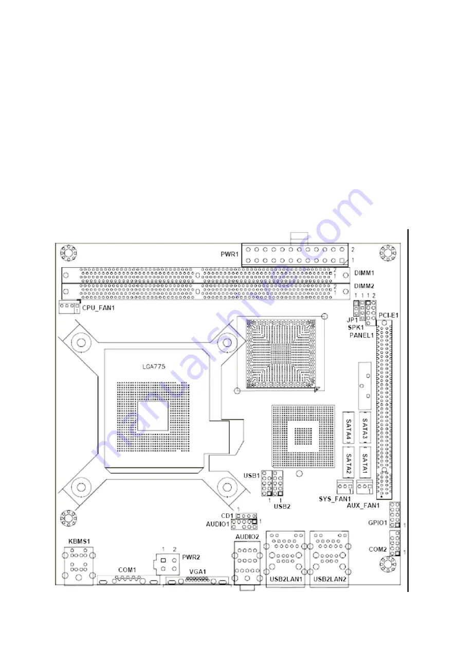
This chapter gives the definitions and shows the positions of jumpers, headers and
connectors. All of the configuration jumpers on PEB-7602 board are in the proper position.
The default settings shipped from factory are marked with an asterisk ( ).
In general, jumpers on the Mini ITX are used to select options for certain features. Some of
the jumpers are designed to be user-configurable, allowing for system enhancement. The
others are for testing purpose only and should not be altered. To select any option, cover
the jumper cap over (SHORT) or remove (NC) it from the jumper pins according to the
following instructions. Here, NC stands for “Not Connect”.
2.1 Board
Layout
Summary of Contents for PEB-7602
Page 1: ...PEB 7602 Intel Core 2 Duo Desktop Q965 Mini ITX User s Manual Rev 1 0 2007 04 25 ...
Page 7: ...PEB 7602 User s Manual CHAPTER 1 7 55 ...
Page 13: ...PEB 7602 User s Manual 13 55 1 5 Dimensions Unit mm ...
Page 14: ...PEB 7602 User s Manual CHAPTER 2 14 55 ...
Page 20: ...PEB 7602 User s Manual 20 55 CHAPTER 3 ...
Page 25: ...PEB 7602 User s Manual 25 55 CHAPTER 4 ...
Page 27: ...PEB 7602 User s Manual 27 55 g 4 1 2 Advanced Settin ...
Page 32: ...PEB 7602 User s Manual 32 55 4 1 2 3 Super IO Configuration ...
Page 38: ...PEB 7602 User s Manual 38 55 4 1 2 7 MPS Configuration Select MPS Revision ...
Page 41: ...PEB 7602 User s Manual 41 55 tting 4 1 3 Advanced PCI PnP Se ...
Page 47: ...PEB 7602 User s Manual 47 55 ttings 4 1 6 Advanced Chipset Se ...


