background image

Introduction

ROBO-679 User’s Manual

1-2

1

1-1 Check List

The ROBO-679 package should cover the following basic items accompany with this 
manual.

 One ROBO-679 single board computer

 One Parallel Port cable kit

 One Serial Port cable to support two interfaces

 One FDC cable

 One IDE cable

 One Y-Cable cable for PS/2 Keyboard and Mouse

 One 5-pin to 5-pin keyboard cable for backplane connection

 One 4-pin ATX power control cable for backplane connection

 One CD-Title ROBO-679 to supply Intel 82815 GMCH VGA display driver, Intel 

82801BA ICH2 integrated LAN controller driver.

If any of these items is damaged or missing, please contact your vendor and keep all 
packing materials for future replacement and maintenance.

StockCheck.com

Summary of Contents for ROBO-679

Page 1: ...ingle Board Computer User s Manual P N 861106790047 Version 1 0 Copyright Portwell Inc 1999 All rights reserved All other brand names are registered trademarks of their respective owners S t o c k C h e c k c o m ...

Page 2: ... Compatibility Directive 89 336 EEC The equipment was evaluated and passed the test the following standards were applied EMC EN 55022 1994 A1 1995 Class A EN 50082 2 1995 EN 61000 4 2 1995 EN 61000 4 3 1996 EN 61000 4 4 1995 The following manufacturer is responsible for this declaration Portwell Inc Company Name 3F No 88 Sec 1 Nei Hu Rd Taipei Taiwan R O C Company Address Taipei R O C Oct 29 1998 ...

Page 3: ...ast Ethernet Controller 3 6 3 4 4 On board 68 pin PCI connector 3 6 3 5 Clear CMOS Operation 3 7 3 6 Watch Dog Timer Programming 3 7 Chapter 4 BIOS Setup Information 4 1 Entering Setup 4 1 4 2 Main Menu 4 2 4 3 Standard CMOS Setup Menu 4 3 4 4 IDE Adaptors Setup Menu 4 4 4 5 Advanced BIOS Features 4 6 4 6 Advanced Chipset Features 4 9 4 7 Integrated Peripherals 4 13 4 8 Power Management Setup 4 18...

Page 4: ...Chapter 5 Troubleshooting 5 1 Backplane Setup 5 1 5 2 Onboard Hardware Installation 5 5 5 3 BIOS Setting 5 6 5 4 OS Diagnostics 5 7 S t o c k C h e c k c o m ...

Page 5: ... Chapter 4 BIOS Setup Information specifies the meaning of each setup parameters and how to get advanced BIOS performance and update new BIOS In addition POST checkpoint list will give you a guide of trouble shooting Chapter 5 Troubleshooting gives you a few reminding hints in building up a valid and working system with ROBO 679 in terms of hardware and software perspective Issues addressed are ba...

Page 6: ...rd controller one hardware monitor one IrDA port and one parallel port Two high performance 16C550 compatible UARTs provide 16 byte transmit receive FIFOs and the multi mode parallel port supports SPP EPP ECP function Besides three USB Universal Serial Bus ports provide high speed data communication between peripherals and PC PCI type daughter board can also be compatible to ROBO 679 The PICMG sta...

Page 7: ...le One IDE cable One Y Cable cable for PS 2 Keyboard and Mouse One 5 pin to 5 pin keyboard cable for backplane connection One 4 pin ATX power control cable for backplane connection One CD Title ROBO 679 to supply Intel 82815 GMCH VGA display driver Intel 82801BA ICH2 integrated LAN controller driver If any of these items is damaged or missing please contact your vendor and keep all packing materia...

Page 8: ...t in Pentium III Pentium III S processor Chipset Intel 815E B step Chipset Bus Interface Follow PICMG 1 0 Revision 2 0 standard 32 bit PCI and 16 bit ISA Fully complies with PCI Local Bus specification V2 1 support 4 master PCI slots PCI IDE Interface Support two enhanced IDE ports up to four HDD devices with PIO mode 4 and Ultra DMA 33 66 100 mode transfer and Bus Master feature Floppy Drive Inte...

Page 9: ...d lock and HDD active LED Real Time Clock Calendar RTC Support Y2K Real Time Clock calendar with battery backup for 7 year data retention Watchdog Timer Support 255 intervals from 0 5 sec min to 254 5 sec min by software programming Disk On Chip DOC Feature Reserved one 32 pin socket for M systems Flash Disk up to 288MB DOS Windows Win95 NT bootable drivers and Utility supported On board VGA Intel...

Page 10: ...cket Support one Mini DIN one port USB one Ethernet port and one VGA port Physical and Environmental Requirements Outline Dimension L X W 338 5mm 13 33 X 122mm 4 8 PCB layout 6 layer Power Requirements 5V 10A 12V 200mA 12V 30mA Test Configuration CPU Intel PIII 1GHz 133MHz FSB 256KB L2 Cache Memory PC133 SDRAM 256MBx2 Primary Master IDE HDD Seagate ST33232A O S Microsoft Windows 98 Second Edition ...

Page 11: ...s at reduced cost It dynamically allocates and de allocates system memory for complex 3D textures preserving the benefits of standard AGP add in solutions Its 64 bit AGTL based host bus interface optimized 64 bit DRAM interface supports two 3 3V DIMMs at the maximum bus frequency of 100 133 MHz The 32 bit PCI bus interface supports 4 PCI masters for external backplane support The 82801BA Hub emplo...

Page 12: ...or special I O applications and multi ISA slots Besides an advanced feature is used on ROBO 679 to support detecting and monitoring of system temperature operating voltage and fan status The 82802 Firmware Hub stores system BIOS and video BIOS eliminating a redundant nonvolatile memory component There is one on board PCI Fast Ethernet via RJ 45 Ports to support full functionality of ROBO 679 AIO S...

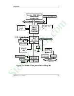
Page 13: ...3 MHz Display Cache Memory 82801BA ICH2 360 EBGA Hub Link PCI BUS PC87200 PCI to ISA Bridge DiskOnChip BUFFER ISA BUS Golden Finger SUPER I O W83627HF MAC WDT Hardware Monitor Figure 1 1 ROBO 679 System Block Diagram IDE 2 IDE 1 IDE Bus Master ULTRA 100 Dual Channel 3 x USB PORTS 82802AB FWH LPC 2UART LPT FDD IR Mouse Keyboard 2 1 Phy ˡ S t o c k C h e c k c o m ...

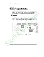
Page 14: ...rked with a star 2 1 Jumpers In general jumpers on the single board computer are used to select options for certain features Some of the jumpers are designed to be user configurable allowing for system enhancement The others are for testing purpose only and should not be altered To select any option cover the jumper cap over Short or remove NC it from the jumper pins according to the following ins...

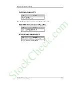
Page 15: ...abled NC Disabled Note Enable JP1 will force system to run with X2 core bus ratio RTC CMOS Clear Jumper Setting JP2 JP2 Function 1 2 Normal Operation 2 3 Clear CMOS Contents AT ATX Power Selection JP3 JP3 Function 3 5 4 6 Select ATX Power Supply 1 3 2 4 Select AT Power Supply S t o c k C h e c k c o m ...

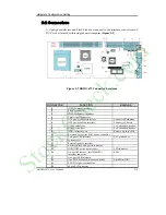
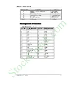
Page 16: ...Backplane J6 ATX power button interface Connect to Chassis J7 COM1 serial port 2 x 5 shrouded header J8 COM2 serial port 2 x 5 shrouded header J9 IrDA infrared port Reserve 6 pin for SIR J10 Reserved for system FAN power connector J11 Two port USB interface 2 x 5 pin header J12 System reset J13 External speaker interface J14 Keyboard lock and power indicator J15 IDE1 IDE2 active status report LED ...

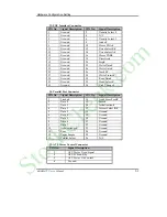
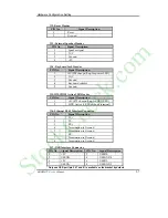
Page 17: ... socket 3 3V SDRAM P Pin Assignments of Connectors J1 J3 IDE1 IDE2 Interface Connector PIN No Signal Description PIN No Signal Description 1 RESET 2 Ground 3 Data 7 4 Data 8 5 Data 6 6 Data 9 7 Data 5 8 Data 10 9 Data 4 10 Data 11 11 Data 3 12 Data 12 13 Data 2 14 Data 13 15 Data 1 16 Data 14 17 Data 0 18 Data 15 19 Ground 20 N C 21 DMA REQ 22 Ground 23 IOW 24 Ground 25 IOR 26 Ground 27 IOCHRDY 28...

Page 18: ...ack 0 27 Ground 28 Write Protect 29 Ground 30 Read Data 31 Ground 32 Head Select 33 Ground 34 Disk Change J4 Parallel Port Connector PIN No Signal Description PIN No Signal Description 1 Strobe 14 Auto Form Feed 2 Data 0 15 Error 3 Data 1 16 Initialization 4 Data 2 17 Printer Select IN 5 Data 3 18 Ground 6 Data 4 19 Ground 7 Data 5 20 Ground 8 Data 6 21 Ground 9 Data 7 22 Ground 10 Acknowledge 23 ...

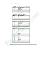
Page 19: ...ound GND 6 Data Set Ready DSR 7 Request to Send RTS 8 Clear to Send CTS 9 Ring Indicator RI 10 N C J9 Standard IrDA Header PIN No Signal Description 1 VCC 5V 2 IOVSB 3 IRRX 4 Ground 5 IRTX 6 OVCROFF Over Current Off J10 J19 Chassis CPU Fan Power Connector PIN No Signal Description 1 Ground 2 12V 3 Pull up 5V For tachometer sense signal J11 USB Interface Connector 2x5 Pin Header PIN No Signal Descr...

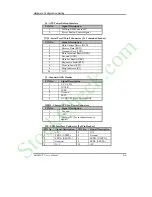
Page 20: ... IDE1 IDE2 Active LED Header PIN No Signal Description 1 5V 470 ohm pull up for HDD LED 2 HDD Active LED cathode terminal J16 Ethernet RJ 45 Interface Connector PIN No Signal Description 1 TX 2 TX 3 RX 4 Termination to Ground 5 Termination to Ground 6 RX 7 Termination to Ground 8 Termination to Ground J17 USB Interface Connector PIN No Signal Description PIN No Signal Description 1 5V 2 USBD0 3 US...

Page 21: ... Clock J21 Standard 5 1 4 disk power connector PIN No Signal Description 1 12V 2 GND 3 GND 4 5V J22 External Keyboard Connector PIN No Signal Description 1 Keyboard Clock 2 Keyboard Data 3 N C 4 Ground 5 5V J23 VGA D5VB 15 Connector PIN No Signal Description 1 R 2 G 3 B 4 N C 5 Ground 6 Ground 7 Ground 8 Ground 9 N C 10 Ground 11 N C 12 MONID1 13 HSYNC 14 VSYNC 15 MONID2 S t o c k C h e c k c o m ...

Page 22: ... GND 21 VCC 22 AD16 23 AD17 24 AD18 25 AD19 26 AD20 27 AD21 28 AD22 29 AD23 30 GND 31 VCC 32 AD24 33 AD25 34 AD26 35 AD27 36 AD28 37 AD29 38 AD30 39 AD31 40 GND 41 VCC 42 BE 0 43 BE 1 44 BE 2 45 BE 3 46 PAR 47 Frame 48 TRDY 49 IRDY 50 GND 51 VCC 52 STOP 53 Devsel 54 Reserved for PERR 55 SERR 56 REQ 4 57 GNT 4 58 Reserved for REQ 3 59 Reserved for GNT 3 60 GND 61 PCI Clock1 62 PCI Clock2 63 PCIRST ...

Page 23: ...til it fits into place If this operation is not easy or smooth don t do it forcibly You need to check and rebuild the CPU pin uniformly 3 Push down the lever to lock processor chip into the socket 4 Follow the installation guide of cooling fan or heat sink to mount it on CPU surface and lock it on the socket 370 Removing CPU 1 Unlock the cooling fan first 2 Lift the lever of CPU socket outwards an...

Page 24: ...u can install different size of DRAM module on DIMM1 DIMM2 or all to make the system boot Watch out the contact and lock integrity of memory module with socket it will impact on the system reliability Follow normal procedures to install your DRAM module into memory socket Before locking make sure that all modules have been fully inserted into the card slots NOTE 1 To maintain system stability don ...

Page 25: ...System Installation ROBO 679 User s Manual 3 3 S t o c k C h e c k c o m ...

Page 26: ...oles on the socket Make sure that the notched corner or dot mark pin 1 of DOC corresponds to notched corner of the socket Then press the DOC gently until it fits into place If installation procedure is correct the Flash disk can be viewed as a normal hard disk to access read write data WARNING Please ensure that your DOC is properly inserted Placing the DOC in reverse will cause severe damage Reme...

Page 27: ... do not work due to bad contact of golden finger and ISA bus slot It is recommended to apply 4 pin 5 1 4 IDE device power connectors from your power supply onto J21 to ensure a sufficient current supply NOTE Please refer to section 3 4 1 to 3 4 3 to install INF VGA LAN drivers 3 4 1 INF Chipset Component Driver Intel 82815 GMCH chipset is a new chipset that a few old operating systems might not be...

Page 28: ...ere is any In this case onboard 82815 GMCH graphic features will be disabled Drivers Support Please find Intel 82815 GMCH driver in Graphics directory of ROBO 679 CD title Drivers support Windows 3 1 Windows 95 98 98SE Windows NT 3 51 4 0 Windows 2000 and Linux 1 Windows 95 98 98SE Please execute Graphics win9x Win9xm631 exe 2 Windows NT 4 0 Please install Windows NT 4 0 Service Pack 4 or above fi...

Page 29: ... Intel 82801BA MAC Fast Ethernet should appear as Intel R PRO 100 VE Network Connection On board LED Indicator for LAN status ROBO 679 provides three LED indicators to report 82801BA MAC Fast Ethernet interfaces status Please refer to the table below as a quick reference guide Operation of Ethernet Port Intel 82801BA MAC Name of LED ON Off LED1 LAN Link Integrity LED Good link in 10 or 100 Mbps Ba...

Page 30: ...e the JP2 back to 1 2 position Normal Operation and start the system System will then produce a CMOS Check Sum Error message and hold up Users may then follow the displayed message to load in BIOS default setting 3 6 Watch Dog Timer Programming The enable and disable options can be selected in Watch Dog Timer Select of Integrated Peripherals of BIOS Apart from enable and disable options there are ...

Page 31: ...ficant enough to abort the start up 4 1 Entering Setup Turn on or reboot the computer When the message Hit DEL if you want to run SETUP appears press Del key immediately to enter BIOS setup program If the message disappears before you respond but you still wish to enter Setup please restart the system to try COLD START again by turning it OFF and then ON or touch the RESET button You may also rest...

Page 32: ...oad the fail safe defaults from BIOS default table F7 key Load the optimized defaults F10 key Save all the CMOS changes and exit 4 2 Main Menu Once you enter ROBO 679 AWARD BIOS CMOS Setup Utility you should start with the Main Menu The Main Menu allows you to select from eleven setup functions and two exit choices Use arrow keys to switch among items and press Enter key to accept or bring up the ...

Page 33: ...6K Total Memory 261120K Item Help ____________________________ Menu Level Change the day month year and century Move Enter Select PU PD Value F10 Save ESC Exit F1 General Help F5 Previous Values F6 Fail Safe Defaults F7 Optimized Defaults Menu seletions Item Options Description Date Mm dd yy Set the system date Note that the Day automatically changes when you set the date Time Hh mm ss Set the sys...

Page 34: ...uring boot up Extended Memory N A Displays the amount of extended memory detected during boot up Total Memory N A Displays the total memory available in the system 4 4 IDE Adaptors Setup Menu The IDE adapters control the IDE devices such as hard disk drive or cdrom drive It uses a separate sub menu to configure each hard disk drive Screen shot CMOS Setup Utility Copyright 1984 2001 Award Software ...

Page 35: ...ns NONE Access Mode CHS LBA Large Auto Choose the access mode for this hard disk Capacity Auto Display your disk drive size Disk drive capacity Approximated Note that this size is usually slightly greater than the size of a formatted disk given by a disk checking program The following options are selectable only if the IDE Primary Master item is set to Manual Cylinder Min 0 Max 65535 Set the numbe...

Page 36: ...oot Device CDROM Fourth Boot Device ZIP100 Boot Up NumLock Status On Security Option Setup PS 2 Mouse Function Control Enabled OS Select For DRAM 64MB Non OS2 HDD S M A R T Capability Disabled Item Help ___________________________________ Menu Level Move Enter Select PU PD Value F10 Save ESC Exit F1 General Help F5 Previous Values F6 Fail safe defaults F7 Optimized Defaults Virus Warning Enabled A...

Page 37: ... Third Fourth Boot Device The BIOS attempts to load the operating system from the devices in the sequence selected in these items The Choice Floppy LS120 ZIP100 HDD SCSI CDROM LAN and Disabled Boot Up NumLock Status Select power on state for NumLock The choice Off On Security Option Select whether the password is required every time the system boots or only when you enter setup System The system w...

Page 38: ...y PS 2 Mouse Function Control Disabled prevents any installed PS 2 mouse from functioning but frees up IRQ 12 Enabled allows the operating system to determine whether to enable or disable the mouse OS Select For DRAM 64MB Select the operating system that is running with greater than 64MB of RAM on the system The choice Non OS2 OS2 HDD S M A R T Capability This option allows users to enable disable...

Page 39: ...AM Cycle Time Tras Trc Auto SDRAM RAS to CAS Delay Auto SDRAM RAS Precharge Time Auto System BIOS Cacheable Enabled Video BIOS Cacheable Enabled Memory Hole AT 15 16M Disabled Delayed Transaction Enabled Display Cache Frequency 100 MHz System Memory Frequency Auto On Chip Video Window Size 64MB Onboard Display Cache Setting CAS Latency 3 Paging Mode Control Open RAS toCAS Override by CAS LT RAS Ti...

Page 40: ...and If your system installs good quality of SDRAM you can set this option to 3 SCLKs to obtain better memory performance Normally the option will be set to Auto The Choice 2 3 SCLKs or Auto SDRAM RAS Precharge Time This option controls the number of SCLKs for RAS precharge If your system installs good quality of SDRAM you can set this option to 3 SCLKs to obtain better memory performance It is set...

Page 41: ...bled Delayed Transaction Select Enabled to enable delay transaction This will enhance performance for data transmission between different PCI bus The Choice Enabled Disabled Display Cache Frequency This option allows users to configure the display cache frequency The default setting is 100MHz The Choice 100MHz 133MHz System Memory Frequency This option allows users to configure the system memory f...

Page 42: ...ages open or pages close The Choice Open Close RAS to CAS Override This option selects in units of display cache clock periods indicates the RAS to CAS delay The Choice by CAS LT Override 2 RAS Timing This option controls RAS active to precharge and refresh to RAS active delay The Choice Fast Slow RAS Precharge Timing This option controls RAS precharge in local memory clocks The Choice Fast Slow S...

Page 43: ...assword Enter Hot Key Power On Ctrl F1 Onboard FDC Controller Enabled Onboard Serial Port 1 Auto Onboard Serial Port 2 Auto UART Mode Select Normal RxD TxD Active Hi Lo IR Transmission Delay Enabled UR2 Duplex Mode Half Onboard Parallel Port 378 IRQ7 Parallel Port Mode ECP EPP Mode Select EPP1 7 ECP Mode Use DMA 3 PWRON After PWR Fail off Watch Dog Timer Select Disabled DOC Memory Address Range D8...

Page 44: ...DE hard drive supports it and the operating environment includes a DMA driver Windows 95 OSR2 or a third party IDE bus master driver If your hard drive and your system software both support Ultra DMA 33 66 100 select Auto to enable BIOS support The Choice Auto Disabled USB Controller This item allows you to enable disable USB Universal Serial Bus function The choice Enabled Disabled USB Keyboard S...

Page 45: ...on using customized password string Hot Key Power on using special customized key Mouse Left Power on using mouse left click Mouse Right Power on using mouse right click Any Key Power on using any keyboard key Keyboard Power On Password In the event of Power On Function being configured as Password this item will be enabled for tuning Press Enter key to enter a customized password and confirm agai...

Page 46: ...ion IrDA Select IrDA mode transmission ASKIR Select ASKIR mode transmission As Infrared transmission function shares onboard serial port 2 COM2 needs to be enabled RxD TxD Active This item is to configure Infrared transmission rate Four options are available Hi Hi High rate for receiving High rate for transmitting Hi Lo High rate for receiving Low rate for transmitting Lo Hi Low rate for receiving...

Page 47: ...3 1 PWRON After PWR Fail This item allows user to configure the power status of using ATX power supply after a serious power loss occurs On System automatically restores power back Off System stays at power off Former Sts System restores back to previous status On or Off Watch Dog Timer Select This option is used to enable or disable Watch Dog Timer The options are 10 sec 20 sec 30 sec 40 sec 1 mi...

Page 48: ...Thermal Throttling 50 0 Resume by Alarm Disabled Date of Month Alarm 0 Time hh mm ss Alarm 0 0 0 Reload Global Timer Events Primary IDE 0 Disabled Primary IDE 1 Disabled Secondary IDE 0 Disabled Secondary IDE 1 Disabled FDD COM LPT Port Disabled Item Help _____________________________ Menu Level Move Enter Select PU PD Value F10 Save ESC Exit F1 General Help F5 Previous Values F6 Fail Safe Default...

Page 49: ... system to turn off the vertical and horizontal synchronization ports and write blanks to the video buffer Blank Screen This option only writes blanks to the video buffer DPMS Initial display power management signaling Video Off In Suspend This allows user to enable disable video off in Suspend Mode The choices Yes No Suspend Type Two options are available Stop Grant and Power On Suspend Suspend M...

Page 50: ... choices Enabled Disabled Resume by Alarm This item allows users to enable disable the resume by alarm function When Enabled is selected system using ATX power supply could be powered on if a customized time and day is approached Date of Month Alarm When Resume by Alarm is enabled this item could allow users to configure the date parameter of the timing dateline on which to power on the systm The ...

Page 51: ...so as to keep system out of suspend mode if the associated device is busy The choices Enabled Disabled FDD COM LPT Port This item is to configure floppy device COM ports and parallel port being monitored by system so as to keep system out of suspend mode if the associated device is busy The choices Enabled Disabled S t o c k C h e c k c o m ...

Page 52: ...ign IRQ For USB Enabled PCI Slot4 IRQ Assign Auto PCI Slot1 IRQ Assign Auto PCI Slot2 IRQ Assign Auto PCI Slot3 IRQ Assign Auto Item Help Menu Level BIOS can automatically configure all the boot and Plug and Play compatible devices If you choose Auto you cannot select IRQ DMA and memory base address fields since BIOS automatically assigns them Move Enter Select PU PD Value F10 Save ESC Exit F1 Gen...

Page 53: ...rmine the IRQ assigned to the ISA bus and is not available to any PCI slot Legacy ISA for devices compliant with the original PC AT bus specification PCI ISA PnP for devices compliant with the Plug and Play standard whether designed for PCI or ISA bus architecture The Choice Legacy ISA and PCI ISA PnP DMA Resources When resources are controlled manually assign each system DMA channel a type depend...

Page 54: ... Manual 4 24 PCI Slot4 1 2 3 IRQ Assign This BIOS option can assist users to assign IRQ numbers to particular slots The IRQ number availabled are 3 4 5 7 9 10 11 12 14 and 15 Auto is the default value for each slot S t o c k C h e c k c o m ...

Page 55: ...8к 100л Current CPU Temperature 43к 109л System Fan J10 Speed 0 RPM CPU Fan J19 Speed 5314 RPM Vcore 1 63 V Vcc1 8 1 85 V Vcc3 3 3 31 V 5 V 4 94 V 12 V 11 97 V 12 V 12 36 V 5 V 5 04 V VBAT V 3 15 V 5VSB V 4 87 V Item Help Menu Level Move Enter Select PU PD Value F10 Save ESC Exit F1 General Help F5 Previous Values F6 Fail Safe Defaults F7 Optimized Defaults S t o c k C h e c k c o m ...

Page 56: ...U HOST PCI Clock PC133 This item allows you to select CPU Host and the corresponding PCI Clock Since CPU Host and PC133 will be automatically detected different combinations of CPU and DIMM will produce different option table Please refer to the following table as a quick reference guide Based on the FSB of the processor used default value of CPU Host will be automatically detected as 66MHz 100MHz...

Page 57: ... 115 38Mhz No Default 100 33Mhz No 103 34Mhz No 105 35Mhz No 110 37Mhz No 115 38Mhz No 133MHz Processor PIII 667EB PIII 1 26G EB Default 133 33Mhz No 137 34Mhz No 140 35Mhz No 145 36Mhz No 150 37Mhz No 160 38Mhz No 166 42Mhz No Default 133 33Mhz Yes 137 34Mhz Yes 140 35Mhz Yes 145 36Mhz Yes 150 37Mhz Yes 160 38Mhz Yes 166 42Mhz Yes Only Engineering Sample Processor is allowed to be configured with...

Page 58: ...or optimal performance system operations 4 13 Supervisor User Password Setting You can set either supervisor or user password or both of then The differences between are supervisor password can enter and change the options of the setup menus user password just can only enter but do not have the right to change the options of the setup menus When you select this function the following message will ...

Page 59: ...s Setup Menu and its Security option see Section 3 If the Security option is set to System the password will be required both at boot and at entry to Setup If set to Setup prompting only occurs when trying to enter Setup 4 14 Exiting Selection Save Exit Setup Pressing Enter on this item asks for confirmation Save to CMOS and EXIT Y N Y Pressing Y stores the selections made in the menus in CMOS a s...

Page 60: ... the following messages may be displayed if the BIOS detects an error during the POST This list includes messages for both the ISA and the EISA BIOS CMOS BATTERY HAS FAILED CMOS battery is no longer functional It should be replaced CMOS CHECKSUM ERROR Checksum of CMOS is incorrect This can indicate that CMOS has become corrupt This error may have been caused by a weak battery Check the battery and...

Page 61: ...gured incorrectly Also be sure the card is installed firmly in the slot EISA Configuration Is Not Complete PLEASE RUN EISA CONFIGURATION UTILITY The slot configuration information stored in the EISA non volatile memory is incomplete Note When either of these errors appear the system will boot in ISA mode which allows you to run the EISA Configuration Utility ERROR ENCOUNTERED INITIALIZING HARD DRI...

Page 62: ...his location along with the memory map for your system to find and replace the bad memory chips Memory parity Error at Indicates a memory parity error at a specific location You can use this location along with the memory map for your system to find and replace the bad memory chips MEMORY SIZE HAS CHANGED SINCE LAST BOOT Memory has been added or removed since the last boot In EISA mode use Configu...

Page 63: ...ars the system will boot in ISA mode which allows you to run the EISA Configuration Utility Should Have EISA Board But Not Found PLEASE RUN EISA CONFIGURATION UTILITY The board installed is not responding to the ID request or no board ID has been found in the indicated slot NOTE When this error appears the system will boot in ISA mode which allows you to run the EISA Configuration Utility Slot Not...

Page 64: ...sk s fail 40 HDD controller diagnostics failed Hard Disk s fail 20 HDD initialization error Hard Disk s fail 10 Unable to recalibrate fixed disk Hard Disk s fail 08 Sector Verify failed Keyboard is locked out Unlock the key Keyboard error or no keyboard present Cannot initialize the keyboard Make sure the keyboard is attached correctly and no keys are being pressed during the boot BIOS ROM checksu...

Page 65: ...n it will halt the POST process and attempt to display the checkpoint code written to port 80H If the system hangs before the BIOS detects the terminal error the value at port 80H will be the last test performed In this case the terminal error cannot be displayed on the screen The following POST checkpoint codes are valid for all AWARDBIOS products with a core BIOS date of 07 15 95 version 6 27 En...

Page 66: ...by OEM customers 15h Reeserved 16h Initial Early_Init_Onboard_Generator switch 17h Reserved 18h Detect CPU information including brand SMI type Cyrix or Intel and CPU level 586 or 686 19h Reserved 1Ah Reserved 1Bh Initial interrupts vector table If no special specified all H W interrupts are directed to SPURIOUS_INT_HDLR S W interrupts to SPURIOUS_soft_HDLR 1Ch Reserved 1Dh Initial EARLY_PM_INIT s...

Page 67: ...served 32h Reserved 33h Reset keyboard except Winbond 977 series Super I O chips 34h Reserved 35h Reserved 36h Reserved 37h Reserved 38h Reserved 39h Reserved 3Ah Reserved 3Bh Reserved 3Ch Test 8254 3Dh Reserved 3Eh Test 8259 interrupt mask bits for channel 1 3Fh Reserved 40h Test 8259 interrupt mask bits for channel 2 41h Reserved 42h Reserved 43h Test 8259 functionality 44h Reserved 45h Reserved...

Page 68: ...om FDD optional 5Ch Reserved 5Dh 1 Initialize Init_Onboard_Super_IO switch 2 Initialize Init_Onbaord_AUDIO switch 5Eh Reserved 5Fh Reserved 60h Okay to enter Setup utility i e not until this POST stage can users enter the CMOS setup utility 61h Reserved 62h Reserved 63h Reserved 64h Reserved 65h Initialize PS 2 Mouse 66h Reserved 67h Prepare memory size information for function call INT 15h ax E82...

Page 69: ...t power management hook 2 Recover the text fond used by EPA logo not for full screen logo 3 If password is set ask for password 83h Save all data in stack back to CMOS 84h Initialize ISA PnP boot devices 85h 1 USB final Initialization 2 NET PC Build SYSID structure 3 Switch screen back to text mode 4 Set up ACPI table at top of memory 5 Invoke ISA adapter ROMs 6 Assign IRQs to PCI devices 7 Initia...

Page 70: ...ck 5 Build MSIRQ routing table FFh Boot attempt INT 19h 4 17 BIOS Flash Utility Utilize AWARD Flash BIOS programming utility to update on board BIOS for the future new BIOS version Please contact your technical window to get this utility if necessary NOTE Remark or delete any installed Memory Management Utility such as HIMEM SYS EMM386 EXE QEMM EXE etc in the CONFIG SYS files before running Flash ...

Page 71: ...ics 5 1 Backplane Setup Backplane ROBO 679 is a full sized SBC and therefore is able to run on any PICMG backplane active or passive ATX power ROBO 679 is designed to support ATX powering Please refer to the following instruction to apply ATX power on your ROBO 679 and backplane Demonstration model Backplane PBP 14P4 ROBO 679 Step1 Remove the jumper on pin3 and pin4 of CN4 ATX P S CONTROL CONNECTO...

Page 72: ...TX POWER with the CN7 ATX POWER CONNECTOR 20 pin connector on the backplane The CN7 is located on the upper right side of the backplane with white color Step3 Use a 4 pin power cable to connect the CN4 ATX P S CONTROL CONNECTOR 4 pin connector on the backplane S t o c k C h e c k c o m ...

Page 73: ...679 in white color You will also see a mark with J5 at the right top corner of J5 header Connect the 4 pin power control cable with this J5 header Step5 Connect TOGGLE SWITCH with J6 connector on ROBO 679 J6 connector 2 pin is located just on the right side of JP3 jumper of ROBO 679 S t o c k C h e c k c o m ...

Page 74: ... function for the above cabling Please move jumper JP3 to 3 5 short and 4 6 short support ATX function Q How can I build up an AT system using ATX power supply A Do not forget to move JP3 of ROBO 679 back to 1 3 short and 2 4 short support AT function If the ATX power supply has a switch such as ORION 300ATX leave the jumper of backplane connector CN4 in step 1 and use the power supply switch as t...

Page 75: ...ing will not allow you to power on the system 2 Double check if every connector is attached with the correct cable 3 If you have changed processor with different system clock please move JP2 CMOS clear Jumper to 2 3 power on the system to clear CMOS power off the system move JP2 back to 1 2 and power on again Q I power on the system but the CPU speed is not correct Why A This applies to Engineerin...

Page 76: ...n so that you can wake up your system far well Loading the default optimal setting When prompted with the main setup menu please scroll down to Load Optimal Defaults press Enter and Y to load in default optimal BIOS setup This will force your BIOS setting back to the initial factory configuration It is recommended to do this so that you can be sure that system is running with the BIOS setting that...

Page 77: ...iven below for your reference IRQ Description IRQ 0 System Counter IRQ 1 Keyboard IRQ 2 Programmed Controller IRQ 3 COM2 IRQ 4 COM1 IRQ 5 Nothing IRQ 6 Floppy Disk Controller IRQ 7 Printer Port Parallel Port IRQ 8 CMOS Clock IRQ 9 Nothing IRQ 10 USB interface IRQ 11 Nothing IRQ 12 PS 2 mouse IRQ 13 Data Processor IRQ 14 Primary IDE Controller IRQ 15 Secondary IDE Controller It is then very easy to...

Page 78: ... this NT hard disk is installed with FAT16 disk format please boot up your system with any Windows OS You will then be able to see this NT hard disk and retrieve any data you have interest in However if this NT hard disk is installed with NTFS disk format there is only NTFS that allows you to retrieve this NT hard disk again Display setup By default any Windows OS starts with 640 x 480 by 16 color...

Page 79: ... Protocol label and load in the protocols that you have interest generally TCP IP Configuring IP gateway and DNS is required for TCP IP protocol 4 Proceed again Binding after you complete the protocol loading 5 Restart your system 6 There is also situation that your installed network adapter is not working anymore for you or old network driver stays in the system after you change your network card...

Reviews: