Troubleshooting
ROBO-8712E Series User’s Manual
5-2
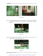
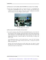
Figure 5-2
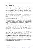
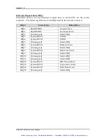
Step 2: And then use 4-pin power cable to connect both ATX P/S Control Connector
on backplane and ATX Power Control (J11) on Signal Board Computer.
(Figure 5-3)
Figure 5-3
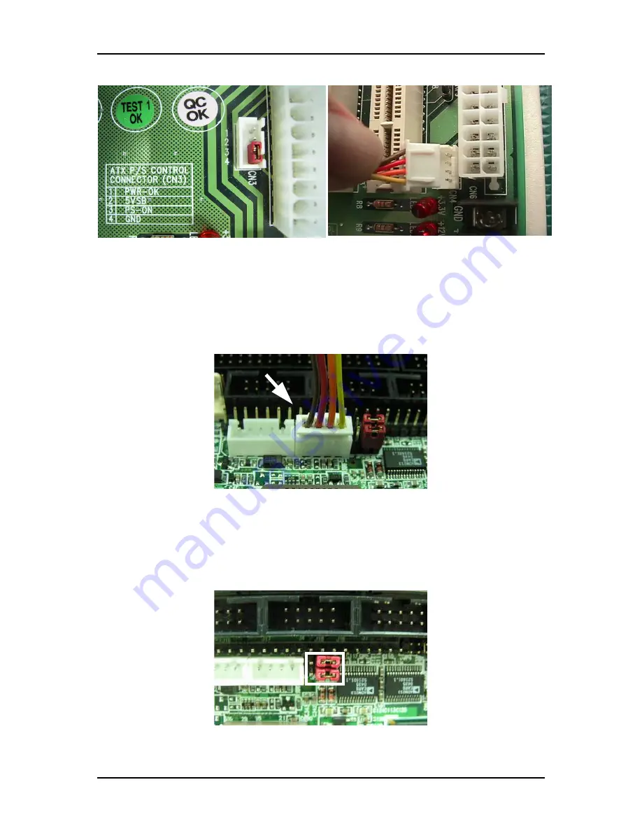
Step 3: Please adjust AT/ATX Jumper on JP3 to short 3-5, 4-6 pins, then it can
support ATX power scheme. (Figure 5-4)
Figure 5-4
Artisan Technology Group - Quality Instrumentation ... Guaranteed | (888) 88-SOURCE | www.artisantg.com

