background image

Troubleshooting 

ROBO-8712E Series User’s Manual 


5-12 

 
disable COM1 serial port to release IRQ #4 
disable COM2 serial port to release IRQ #3 
disable parallel port to release IRQ #7 
disable PS/2 mouse to release IRQ #12, 
…, etc. 
 

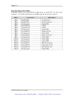
Interrupt Request Lines (IRQ) 

A quick review of the basic IRQ mapping is given below for your reference. 
 

IRQ# 

Description 

IRQ #0 

System Counter 

IRQ #1 

Keyboard 

IRQ #2 

Programmed Controller 

IRQ #3 

COM2 

IRQ #4 

COM1 

IRQ #5 

Display Controller (Shareable) 

IRQ #5 

USB 1.0/1.1 UHCI Controller (Shareable) 

IRQ #6 

Floppy Disk Controller 

IRQ #7 

Print Port (Parallel Port) 

IRQ #8 

CMOS Clock 

IRQ #9 

ACPI Controller (Shareable) 

IRQ #9 

SM BUS Controller (Shareable) 

IRQ #9 

Multimedia Device (Shareable) 

IRQ #10 

USB 1.1 UHCI Controller (Shareable) 

IRQ #10 

Ethernet Controller (Shareable) 

IRQ #11 

Ethernet Controller (Shareable) 

IRQ #11 

USB 2.0 EHCI Controller (Shareable) 

IRQ #12 

PS/2 mouse 

IRQ #13 

Data Processor 

IRQ #14 

Primary IDE Controller 

IRQ #15 

Secondary IDE Controller 

 
It  is  then  very  easy  to  find  out  which  IRQ  resource  is  ready  for  additional 
peripherals. If IRQ resource is not enough, please disable some devices listed above 
to  release  further  IRQ  numbers.  The  IRQ  list  will  show  on  the  Post  sequences  as 
system hardware checking. 


Artisan Technology Group - Quality Instrumentation ... Guaranteed | (888) 88-SOURCE | www.artisantg.com

Summary of Contents for ROBO-8712E Series

Page 1: ...underutilized and idle equipment along with credit for buybacks and trade ins Custom engineering so your equipment works exactly as you specify Critical and expedited services Leasing Rentals Demos In...

Page 2: ...Manual P N B8980851 Version 1 1 Copyright Portwell Inc 2005 All rights reserved All other brand names are registered trademarks of their respective owners Artisan Technology Group Quality Instrumentat...

Page 3: ...5 WDT Function 3 7 3 6 On Board USB 2 0 Controller 3 8 3 7 GPIO 3 9 3 7 1 Pin assignment 3 9 3 7 2 Programming Guide 3 9 Chapter 4 BIOS Setup Information 4 1 4 1 Entering Setup 4 1 4 2 Main Menu 4 2...

Page 4: ...formation Specifies the meaning of each setup parameters how to get advanced BIOS performance and update new BIOS In addition POST checkpoint list will give users some guidelines of trouble shooting C...

Page 5: ...uipment was evaluated and passed the test the following standards were applied EMC EN 55022 1994 A1 1995 Class A EN 50082 2 1991 EN 61000 4 2 1995 EN 61000 4 3 1996 EN 61000 4 4 1995 EN 61000 3 2 1995...

Page 6: ...f This action may damage processor socket which will cause poor contact between CPU socket Handling SBC Caution Do not just hold any single side of the SBC hold evenly on both sides Heavy processor co...

Page 7: ...ded by Portwell s proprietary Omni PCI connector people prefer to have a board with more powerful and more ports on it directly for space saving Echo to the request ROBO 8712EVG2A provides two Gigabit...

Page 8: ...damaged or missing please contact your vendor and keep all packing materials for future replacement and maintenance 1 3 Product Specification Main Features Intel 845GV based PICMG 1 0 SBC with VGA LA...

Page 9: ...up On Board I O PCI IDE Interface Support two enhanced IDE channel up to four HDDs with PIO mode 4 Ultra DMA 33 66 100 model transfer and Bus master feature Floppy Drive Interface Support one FDD port...

Page 10: ...hrough software programming Software programmable time out internal setting Generate system reset Real Time Clock Calendar RTC Support Y2K Real Time Clock Calendar with battery backup for 7 year data...

Page 11: ...ation V2 1 support 4 master PCI slots On Board PCI to ISA Bridge Support ISA Bus mastering Support standard ISA slot 64mA high driving ISA64 High ISA Bus Driving Capability Support 64mA high driving c...

Page 12: ...ies includes two main Intel chips Intel 845GV chipset supports Pentium 4 Celeron D Mobile Pentium 4 M Mobile Celeron processor DDR SDRAM 2D 3D graphic display and ICH4 supports PCI bus interface APM A...

Page 13: ...System Overview ROBO 8712E Series User s Manual 1 7 ROBO 8712E System Block Diagram Artisan Technology Group Quality Instrumentation Guaranteed 888 88 SOURCE www artisantg com...

Page 14: ...d connector All of the configuration jumpers on ROBO 8712E series are in the proper position The default settings shipped from factory are marked with a star 2 1 Jumper Setting 1 1 2 26 13 34 2 1 2 1...

Page 15: ...P3 Process Selection 3 5 4 6 ATX Power Supply 1 3 2 4 AT Power Supply JP4 COM2 RS232 485 422 Selection JP4 Process Selection RS232 5 6 9 11 10 12 15 17 16 18 RS485 1 2 7 9 8 10 19 20 RS422 3 4 7 9 8 1...

Page 16: ...J11 4 Pin Header Backplane 5VSB PS_ON and ATX PWROK PS_ON and ATX PWROK J12 External Keyboard Connector J13 J33 J34 Fan Header J14 Power On Header J15 Reset Header J16 External Speaker Header J17 Keyb...

Page 17: ...ion PIN No Signal Description 1 RESET 2 Ground 3 Data 7 4 Data 8 5 Data 6 6 Data 9 7 Data 5 8 Data 10 9 Data 4 10 Data 11 11 Data 3 12 Data 12 13 Data 2 14 Data 13 15 Data 1 16 Data 14 17 Data 0 18 Da...

Page 18: ...1 20 SA0 21 Data 0 22 Data 1 23 Data 2 24 NC 25 NC 26 NC 27 Data 11 28 Data 12 29 Data 13 30 Data 14 31 Data 15 32 SDCS 3 33 Ground 34 IOR 35 IOW 36 WE 37 INT 38 5V 39 Ground 40 NC 41 RESET 42 IORDY 4...

Page 19: ...ier Detect DCD 2 Receive Data RXD 3 Transmit Data TXD 4 Data Terminal Ready DTR 5 Ground GND 6 Data Set Ready DSR 7 Request to Send RTS 8 Clear to Send CTS 9 Ring Indicator RI 10 N C J9 External Wake...

Page 20: ...J33 J34 Fan Header PIN No Signal Description 1 GND 2 12V 3 Speed Sense to SIO J14 Power On Header PIN No Signal Description 1 5VSB 2 Power On J15 Reset Header PIN No Signal Description 1 Reset 2 GND J...

Page 21: ...IN No Signal Description 1 5V 2 IDEACT J19 IR Header PIN No Signal Description 1 5V 2 NC 3 IRRX 4 GND 5 IRTX 6 NC J20 External SMBus Header PIN No Signal Description 1 SMBCLK 3 GND 4 SMBDATA 5 5v J21...

Page 22: ...ld GND 10 VCC J24 25 Ethernet RJ 45 Interface Connector PIN No Signal Description 1 MDI_2P 2 MDI_0P 3 MDI_0N 4 1 8V 5 MDI_2N 6 MDI_3P 7 GND 8 MDI_1P 9 MDI_1N 10 MDI_3N 11 ACT 12 LINK 13 LINK100 14 LIN...

Page 23: ...nal Description 1 MIC Power 2 AGND 3 LINE IN Left 4 AGND 5 LINE IN Right 6 AGND 7 LINE OUT Left 8 AGND 9 LINE OUT Right J30 D SUB 15 VGA Connector PIN No Signal Description 1 RED 2 GREEN 3 BLUE 4 NC 5...

Page 24: ...23 GND 24 Write Gate 25 GND 26 Track 0 27 GND 28 Write Protect 29 N C 30 Read Data 31 GND 32 N C 33 N C 34 Disk Change J39 Printer Interface Connector PIN No Signal Description PIN No Signal Descripti...

Page 25: ...of CPU socket outwards and upwards to the other end 2 Align the processor pins with pinholes on the socket Make sure that the notched corner or dot mark pin 1 of the CPU corresponds to the socket s be...

Page 26: ...ty and stability don t use memory module without brand You can also use only one double sided DIMM in either one DIMM slot or two single sided DIMM in both slots Watch out the contact and lock integri...

Page 27: ...operly inserted and fixed by mechanism Otherwise the system might be unstable or do not work due to bad contact of PICMG 1 0 PCI plus ISA bus slot Note Please refer to section 3 4 1 to 3 4 3 to instal...

Page 28: ...on board VGA an add on PCI or ISA VGA card can take over the system display Drivers Support Please find 845G GV GMCH driver in the ROBO 8712E series CD title Drivers support Windows 98 98SE 2000 XP Wi...

Page 29: ...ow as a quick reference guide Operation of Ethernet Port 82551QM Name of LED ON OFF Green LAN Linked Active LED Linked Active Blinking Green LAN speed LED 100 Mbps 10 Mbps LED Indicator for LAN status...

Page 30: ...Normal Operation 2 3 Short Clear CMOS contents To correctly operate CMOS Clear function users must turn off the system move JP1 jumper to short pin 2 and 3 To clear CMOS contents please turn the power...

Page 31: ...ll a non zero value into the Time out Value Register to enable refresh WDT System will be reset after the Time out Value to be counted down to zero Or user can directly fill a zero value into Time out...

Page 32: ...ction Mode outp 0x002E 0xAA Definitions of Variables Value of Count mode Register 1 0x00 Count down in seconds Bit3 0 2 0x08 Count down in minutes Bit3 1 Value of Time out Value Register 1 0x00 Time o...

Page 33: ...Port 5 GPIO14 7 General Purpose I O Port 6 GPIO15 8 General Purpose I O Port 7 GPIO16 9 General Purpose I O Port 8 GPIO17 10 5V 3 7 2 Programming Guide There are 8 GPIO pins on ROBO 8712E series These...

Page 34: ...port for input pin get status from the related bit for output pin write value to the related bit For example LD7_CRF0h_Bit4 P0 Let GPIO14 as output pin LD7_CRF2h_Bit4 P0 Let CRF1_Bit4 non inverted LD7...

Page 35: ...port 3 Bit7 vs GPIO port 4 Value of Inversion Register Only high nibble is available for this function When set to a 1 the incoming outgoing port value is inverted When set to a 0 the incoming outgoin...

Page 36: ...ge Hit DEL if you want to run SETUP appears press Del key immediately to enter BIOS setup program If the message disappears before you respond but you still wish to enter Setup please restart the syst...

Page 37: ...ity Standard CMOS Features Advanced BIOS Features Advanced Chipset Features Integrated Peripherals Power Management Setup PnP PCI Configurations PC Health Status Frequency Voltage Control Load Fail Sa...

Page 38: ...ve None Drive A 1 4M 3 5 in Drive B None Video EVG VGA Base Memory 640K Extended Memory 1039360K Total Memory 1040384K Menu Level Change the day month year and century Move Enter Select PU PD Value F1...

Page 39: ...boot up Total Memory N A Displays the total memory available in the system 4 4 IDE Adaptors Setup Menu The IDE adapters control the IDE devices such as hard disk drive or cdrom drive It uses a separat...

Page 40: ...arge Auto Choose the access mode for this hard disk Capacity Auto Display your disk drive size Disk drive capacity Approximated Note that this size is usually slightly greater than the size of a forma...

Page 41: ...D 1 Third Boot Device ZIP100 Boot Other Device Enabled Swap Floppy Drive Disabled Boot up Floppy Seek Enabled Boot up NumLock Status On Gate A20 Option Normal Typematic Rate Setting Disabled X Typemat...

Page 42: ...d and someone attempt to write data into this area BIOS will show a warning message on screen and alarm beep Enabled Activates automatically when the system boots up causing a warning message to appea...

Page 43: ...py drives choose enable to assign physical driver B to logical drive A and Vice Versa The choice Enabled Disabled Boot Up Floppy Seek Enabled tests floppy drives to determine whether they have 40 or 8...

Page 44: ...em will boot but access to Setup will be denied if the correct password is not entered at the prompt APIC Mode The choice Enabled Disabled MPS Version Control For OS The choice 1 1 1 4 OS Select For D...

Page 45: ...ime min Timeout for connection The choice 1 2 4 and 8 Agent after boot Keep Agent running after OS boot The choice Enabled Disabled Small Logo EPA Show The choice Enabled Disabled Artisan Technology G...

Page 46: ...X CAS Latency Time 2 5 X Active to Precharge Delay 7 X DRAM RAS to CAS Delay 3 X DRAM RAS Precharge 3 Memory Frequency For Auto System BIOS Cacheable Enabled Video BIOS Cacheable Enabled Memory Hole A...

Page 47: ...This option controls the number of SCLKs SDRAM Clock from a row activate command to a read or write command If your system installs good quality of SDRAM you can set this option to 3 SCLKs to obtain b...

Page 48: ...memory is reserved for ISA cards This memory must be mapped into the memory space below 16MB The choice Enabled Disabled Delayed Transaction Select Enabled to enable delay transaction This will enhanc...

Page 49: ...B Mouse Support Disabled Init Display First PCI Slot IDE HDD Block Mode Enabled POWER ON Function BUTTON ONLY X KB Power ON Password Enter X Hot Key Power ON Ctrl F1 Onboard FDC Controller Enabled Onb...

Page 50: ...to Mode 0 Mode 1 Mode 2 Mode 3 and Mode 4 IDE Primary Secondary Master Slave UDMA Ultra DMA 33 66 100 implementation is possible only if your IDE hard drive supports it and the operating environment i...

Page 51: ...password string Hot Key Power on using special customized key Mouse Left Power on using mouse left click Mouse Right Power on using mouse right click Any Key Power on using any keyboard key Button On...

Page 52: ...function shares onboard serial port 2 COM2 needs to be enabled RxD TxD Active This item is to configure Infrared transmission rate Four options are available Hi Hi High rate for receiving High rate fo...

Page 53: ...Mode Select Select different version of EPP mode The choice EPP1 7 EPP1 9 ECP Mode Use DMA Select a proper DMA channel for ECP mode The choice 3 1 PWRON After PWR Fail This item allows user to config...

Page 54: ...f by PWR BTTN Instant Off CPU THRM Throttling 50 0 Wake up by On Board LAN Disabled Power On by Ring Disabled X USB KB Wake Up From S3 Disabled Resume by Alarm Disabled X Date of Month Alarm 0 X Time...

Page 55: ...n User Defined Allow you to set each mode individually When not disabled Suspend Mode ranges from 1 min to 1 Hour and HDD Power Down ranges from 1 Min to 15 Min Video Off Method This determines the ma...

Page 56: ...ff by PWR BTTN This item allows users to set the time to remove the power after the power button is pressed The choice Instant Off Delay 4 Sec CPU THRM Throttling When the CPU temperature reaches the...

Page 57: ...ure the time parameter of the timing dateline on which to power on the system The choice hh 0 23 mm 0 59 ss 0 59 Primary Secondary IDE 0 1 This item is to configure IDE devices being monitored by syst...

Page 58: ...in 2 Assignment Auto INT Pin 3 Assignment Auto INT Pin 4 Assignment Auto INT Pin 5 Assignment Auto INT Pin 6 Assignment Auto INT Pin 7 Assignment Auto INT Pin 8 Assignment Auto Menu Level Select Yes i...

Page 59: ...I ISA PnP for devices compliant with the plug and play standard whether designed for PCI or ISA bus architecture The choice PCI ISA PnP Legacy ISA DMA Resources When resources are controlled manually...

Page 60: ...I Cntrlr Bus 0 Dev 29 Func 2 The choice Auto 3 4 5 7 9 10 11 12 14 and 15 INT Pin 4 Assignment Devices S using this INT USB 1 0 1 1 UHCI Cntrlr Bus 0 Dev 29 Func 1 The choice Auto 3 4 5 7 9 10 11 12 1...

Page 61: ...F1 General Help F5 Previous Values F6 Fail Safe Defaults F7 Optimized Defaults CPU Warning Temperature This item allows you to set a temperature above which the system will start the beeping warning...

Page 62: ...ults from the main menu shows you two options which are described below Load Fail Safe Defaults When you press Enter on this item you get a confirmation dialog box with a message similar to Load Fail...

Page 63: ...nter a password To disable a password just press Enter when you are prompted to enter the password A message will confirm the password will be disabled Once the password is disabled the system will bo...

Page 64: ...xt time you boot your computer the BIOS configures your system according to the Setup selections stored in CMOS After saving the values the system is restarted again Exit Without Saving Pressing Enter...

Page 65: ...ether your Backplane is PICMG PCI ISA Backplane please contact with vendor or manufacturer P4 Power Connector ROBO 8712E series requires power drawing from two power connectors J1 and J2 please connec...

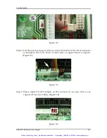
Page 66: ...S Control Connector on backplane and ATX Power Control J11 on Signal Board Computer Figure 5 3 Figure 5 3 Step 3 Please adjust AT ATX Jumper on JP3 to short 3 5 4 6 pins then it can support ATX power...

Page 67: ...s used to power on ATX Power Supply Generally the TOGGLE SWITCH is located on the chassis of front panel Figure 5 5 Step 6 The figure below is the TOGGLE SWITCH which is used to switch the ATX Power o...

Page 68: ...Figure 5 7 Figure 5 7 Step 2 Please adjust AT ATX Jumper on JP3 to short 1 3 2 4 pins then it can support AT power scheme Figure 5 8 Figure 5 8 Step 3 Turn on the Power Supply then system will boot up...

Page 69: ...ch current on the 5V loading Step 1 Please connect 4 pins IDE power connector to J2 in order to make system stand alone See Figure 5 9 Figure 5 9 Step 2 Please connect 12V Power connector to CPU suppl...

Page 70: ...ing Beep sounds Meaning Action One long beep with one short beeps DRAM error Change DRAM or reinstall it One long beep constantly DRAM error Change DRAM or reinstall it One long beep with two short be...

Page 71: ...sor or Mobile Intel Pentium 4 Processor On the contrary please leave the jumper J32 open for using the Intel Pentium 4 Processor with Hyper Threading Technology and Intel Pentium 4 Celeron Processor Q...

Page 72: ...If the ATX power supply has a switch such as ORION 330ATX 12V do not remove the jumper of Backplane connector in step 1 and use the power supply switch as the system power on switch In all cases users...

Page 73: ...ar CMOS move on off switch from off to on for AT mode or toggle the switch for ATX mode power off the system move JP1 back to 1 2 and power on again This way to process the action for Clear the CMOS S...

Page 74: ...ble with Terminator to the SCSI HDD which to have this function ready When you are using the SCSI devices please connect the SCSI Flat cable with Terminator to the SCSI HDD When system boot up the sys...

Page 75: ...recommended to do this so you can be sure the system is running with the BIOS setting that Portwell has highly endorsed As a matter of fact users can load the default BIOS setting any time when system...

Page 76: ...Parallel Port IRQ 8 CMOS Clock IRQ 9 ACPI Controller Shareable IRQ 9 SM BUS Controller Shareable IRQ 9 Multimedia Device Shareable IRQ 10 USB 1 1 UHCI Controller Shareable IRQ 10 Ethernet Controller...

Page 77: ...rrupt Area 0040 004F 0 3K BIOS Data Area 0050 006F 0 5K System Data 0070 0483 16K DOS 0484 085B 15K Program Area 085C 9F7F 604K Available 9F7F 9FFF 2K Unused Conventional memory ends at 638K A000 AFFF...

Page 78: ...t IRQ 2 Unassigned Usable IRQ IRQ 3 System ROM COM 2 IRQ 4 System ROM COM 1 IRQ 5 Unassigned Usable IRQ IRQ 6 System ROM Diskette Event IRQ 7 Unassigned Usable IRQ IRQ 8 System ROM Real Time Clock IRQ...

Page 79: ...uipment Have surplus equipment taking up shelf space We ll give it a new home Learn more Visit us at artisantg com for more info on price quotes drivers technical specifications manuals and documentat...

Reviews: