background image

XR520 User’s Manual

8

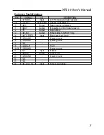
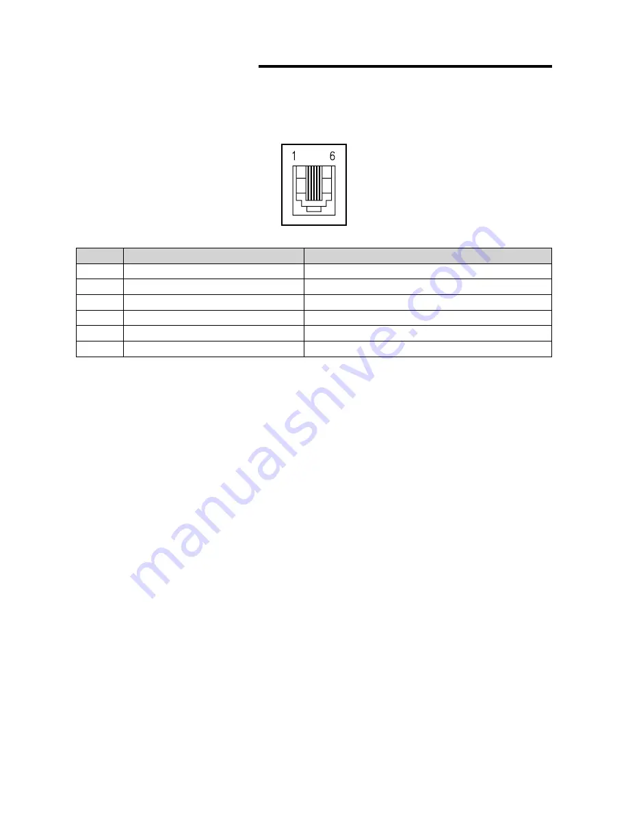
2-2-2. Cash Drawer Connector

The printer can operate two cash drawers with a 6 pin RJ-11 modular connector. 

The driver is capable of supplying a maximum current of 1.0A/24VDC for 510ms or less 

when not printing.

PIN

SIGNAL

DESCRIPTION

1

Signal GND

-

2

Drawer kick-out drive signal 1

Output

3

Drawer open/close signal

Input

4

+24V

-

5

Drawer kick-out drive signal 2

Output

6

Signal GND

-

Caution : To avoid an overcurrent, the resistance of the drawer kick-out solenoid must be 24 Ω 


or more.

Summary of Contents for XR520

Page 1: ...hat Now support POSMicro com Monday Friday 6 AM to 5 PM Pacific Time Bulk Discounts FREE SHIPPING SE Habla Espa ol Free ground shipping to the continental USA on orders over 100 For Help Call 1 800 24...

Page 2: ...XR520 Receipt Printer User s Manual...

Page 3: ...5 Year Limited Warranty POS X Inc provides this five 5 Year Warranty for this product For terms and conditions please go to WWW POS X COM All specifications are subject to change without notice...

Page 4: ...ing the Paper Roll 9 3 Control panel and other functions 12 4 Self Test 13 5 Hexadecimal Dump 14 6 Specifications 15 6 1 General Specifications 15 6 2 Auto Cutter Specifications 17 6 3 Interface 17 6...

Page 5: ...ER SWITCH Used to turn on off power to the printer COVER OPEN BUTTON Push down this button to open the printer cover CONTROL PANEL Features LED indicators to indicate printer status and switches to op...

Page 6: ...king Your printer box should include these items If any items are damaged or missing please contact your dealer for assistance P O W E R E R R O R P A P E R F E E D The Printer User s Manual Paper Rol...

Page 7: ...er which is shown below Before connecting any of the cables make sure that both the printer and the computer are turned off For connection to a host computer For connection to a host computer For conn...

Page 8: ...D Output Printer transmit data line RS 232C level 3 RXD Input Printer receive data line RS 232C level 4 20 DTR Output Printer handshake to host line RS 232C level 6 DSR Input Data Send Ready 1 7 GND S...

Page 9: ...ompleted 11 BUSY Output Impossible to print of data receiving 12 PE Output Paper empty 13 SELECT Output Printer status for ON OFF line 14 AUTO FEED Input Paper auto feed signal 15 GROUND System ground...

Page 10: ...e of supplying a maximum current of 1 0A 24VDC for 510ms or less when not printing PIN SIGNAL DESCRIPTION 1 Signal GND 2 Drawer kick out drive signal 1 Output 3 Drawer open close signal Input 4 24V 5...

Page 11: ...the printer cannot detect the paper end correctly Turn off power switch 1 Make sure that the printer is not receiving data Otherwise data may be lost 2 Open the top cover unit by pushing down the cove...

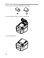
Page 12: ...o note the correct direction that the paper comes off the roll 6 Pull out a small amount of paper as shown Then close the cover P O W E R E R R O R P A P E R F E E D 7 Tear off the paper as shown P O...

Page 13: ...s case repeat power on and off several times If the top cover is still stuck please follow the steps to release the papers from jamming 1 Make sure the printer is turned off 2 Take out cutter cover as...

Page 14: ...n also hold down the FEED button to feed paper continuously 3 2 Error indicators This section explains the different patterns signaled by the three LED indicators located on the top cover of the print...

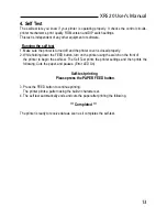
Page 15: ...While holding down the FEED button turn on the printer using the switch on the front of the printer to begin the self test The Self Test prints the printer settings and then prints the following Cuts...

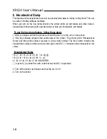
Page 16: ...er you make sure that the printer is off and Dip s w 1 2 is ON turn on the printer 2 Run any software program that sends data to the printer The printer prints Hexadecimal Dump and then all the codes...

Page 17: ...00mm sec Approx 35 4LPS 3 Dot density 180 DPI Hor Ver 180 180 0 141mm 0 141mm dot 4 Printing Width 180 DPI Max 72mm 512 dots 5 Number of print columns No of columns Font A Font B 180 DPI 42 56 6 Roll...

Page 18: ...XR520 User s Manual 16 8 Overall dimension...

Page 19: ...ckness is between 65 and 90 m 6 3 Interface RS232C Serial Interface Centronics Parallel Interface IEEE1284 USB Interface USB COMBO Interface Ethernet Interface 10Mbps 6 4 Electrical Characteristics 1...

Page 20: ...Requirements 1 Operating Temperature 5 C to 40 C Humidity 10 to 90 RH without condensation 2 Transport Storage except paper Temperature 20 C to 60 C Humidity 10 to 90 RH without condensation 6 6 Relia...

Page 21: ...18 ESC 3 Set line spacing 19 ESC Select peripheral device 20 ESC Cancel user defined characters 21 ESC Initialize printer 22 ESC D Set horizontal tab positions 23 ESC E Turn emphasized mode on off 24...

Page 22: ...mode and cut paper 54 GS W Set printing area width 55 GS Set relative vertical print position in page mode 56 GS a Enable disable Automatic Status Back ASB 57 GS f Select font for HRI characters 58 G...

Page 23: ...XR520 User s Manual 21...

Page 24: ...XR520 User s Manual 22...

Page 25: ...Rev 1 0 POS X lnc 1975 Midway Lane Suite O Bellingham WA 98226 360 738 8433 support pos x com...

Reviews: