105
5. BIOS Setup Utility
* This chapter tells how to change the system settings through the BIOS Setup menus.
Detailed descriptions of the BIOS parameters are also provided.
(1) BIOS setup program
This motherboard supports a programmable firmware chip that you can update using the provided utility described in
section “2.1 Managing and updating your BIOS.”
Use the BIOS Setup program when you are installing a motherboard, reconfiguring your system, or prompted to “Run
Setup”. This section explains how to configure your system using this utility.
Even if you are not prompted to use the Setup program, you can change the configuration of your computer in the
future. For example, you can enable the security password feature or change the power management settings. This
requires you to reconfigure your system using the BIOS Setup program so that the computer can recognize these
changes and record them in the CMOS RAM of the firmware hub.
The firmware hub on the motherboard stores the Setup utility. When you start up the computer, the system provides
you with the opportunity to run this program.
Press <Del> during the Power-On-Self-Test (POST) to enter the Setup utility; otherwise, POST continues with its test
routines.
If you wish to enter Setup after POST, restart the system by pressing <Ctrl+Alt+Delete>, or by pressing the reset
button on the system chassis. You can also restart by turning the system off and then back on. Do this last option only
if the first two failed.
The Setup program is designed to make it as easy to use as possible. Being a menu-driven program, it lets you scroll
through the various sub-menus and make your selections from the available options using the navigation keys.
•
The default BIOS settings for this motherboard apply for most conditions to ensure optimum
performance. If the system becomes unstable after changing any BIOS settings, load the
default settings to ensure system compatibility and stability. Select the Load Default
Settings item under the Exit Menu. See section “2.7 Exit Menu.”
•
The BIOS setup screens shown in this section are for reference purposes only, and may not
exactly match what you see on your screen.
Summary of Contents for BLUO D25
Page 1: ...Point of sale system BLUO D25 Use r manual BLUO_D25_UM_eng_PBUM_E Rev002 140926...
Page 5: ...5 Specification Outside size...
Page 15: ...15 Optional Devices 2nd LCD monitor 12 1 Optional Devices 2nd LCD monitor 10...
Page 20: ...20 Standard I O port...
Page 31: ...31 LCD monitor module Step4 Lift up the LCD monitor module and detach from the Stand...
Page 33: ...33 HDDModule Step4 See printed image for details Zoom in Check an arrow sign...
Page 46: ...46 CDP Option Step7 Reassemble a unit using the Reverse procedure of step 1 3 above...
Page 51: ...51 MSR Option Step3 Assemble the MSR Step4 I O part put holes in the sample place RJ45 PORT...
Page 68: ...68 LPT Option Step10 Reassemble a unit using the Reverse procedure of stpe1 5 above...
Page 72: ...72 USB PCB Option Step8 Use cutter and ripper to remove USB dummy ZOOM IN...
Page 77: ...77 RAM option Step8 Place Mother board as in image Stetp9 Install the Memory ZOOM IN...
Page 78: ...78 RAM option Step10 Assemble the SODIMM from the socket Retaining clip DDR SODIMM notch...
Page 79: ...79 RAM option Step11 Reassemble a unit using the Reverse procedure of stpe1 5 above...
Page 83: ...83 2nd storage HDD Option Step8 Assemble 4 screw from HDD bracket as show above ZOOM IN 1 2...
Page 94: ...94 Cash drawer Option Step8 Use cutter or ripper to remove Io bracket blanking ZOOM IN...
Page 95: ...95 Cash drawer Option Step9 Assemble a hexa bolt and fasten Screw to cash drawer ZOOM IN...
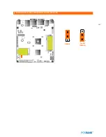
Page 104: ...104 6 OnboardTouch function Enable Disable selection USB_SEL 1 Disable Enable Default 1...
Page 111: ...111 2 4 Launch PXE 0Prom Disable Configuration options Disabled Enabled...
Page 118: ...118 2 10 Hardware Monitor Smart Fan Mode configuration Smart Fan Mode select...
Page 120: ...120 2 11 Chipset...
Page 122: ...122 2 13 Boot Display Configuration...
Page 124: ...124 Color depth 24Bits Select color Depth for LVDS...
Page 125: ...125 2 15 South Bridge parameters Into South Bridge Subdiredtory...
Page 127: ...127 2 16 Boot...


