57
MSR - Option
Step5.
Access to POSBANK homepage
Step6.
Click on the button on the toolbar
(Position : SUPPORT -> Firmware and Drivers )
Step7.
Search the MSR at search engine.
Step8.
Download the MSR mapper file
(file name : [POS Peripherals]MSR Utility _Magnetic
Stripe Reader(MSR) Utility)
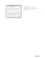
Step9.
Double
click [lpu230 installer] file and
double click the lpu230.msi
Summary of Contents for BLUO D25
Page 1: ...Point of sale system BLUO D25 Use r manual BLUO_D25_UM_eng_PBUM_E Rev002 140926...
Page 5: ...5 Specification Outside size...
Page 15: ...15 Optional Devices 2nd LCD monitor 12 1 Optional Devices 2nd LCD monitor 10...
Page 20: ...20 Standard I O port...
Page 31: ...31 LCD monitor module Step4 Lift up the LCD monitor module and detach from the Stand...
Page 33: ...33 HDDModule Step4 See printed image for details Zoom in Check an arrow sign...
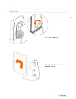
Page 46: ...46 CDP Option Step7 Reassemble a unit using the Reverse procedure of step 1 3 above...
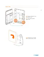
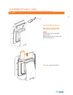
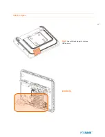
Page 51: ...51 MSR Option Step3 Assemble the MSR Step4 I O part put holes in the sample place RJ45 PORT...
Page 68: ...68 LPT Option Step10 Reassemble a unit using the Reverse procedure of stpe1 5 above...
Page 72: ...72 USB PCB Option Step8 Use cutter and ripper to remove USB dummy ZOOM IN...
Page 77: ...77 RAM option Step8 Place Mother board as in image Stetp9 Install the Memory ZOOM IN...
Page 78: ...78 RAM option Step10 Assemble the SODIMM from the socket Retaining clip DDR SODIMM notch...
Page 79: ...79 RAM option Step11 Reassemble a unit using the Reverse procedure of stpe1 5 above...
Page 83: ...83 2nd storage HDD Option Step8 Assemble 4 screw from HDD bracket as show above ZOOM IN 1 2...
Page 94: ...94 Cash drawer Option Step8 Use cutter or ripper to remove Io bracket blanking ZOOM IN...
Page 95: ...95 Cash drawer Option Step9 Assemble a hexa bolt and fasten Screw to cash drawer ZOOM IN...
Page 104: ...104 6 OnboardTouch function Enable Disable selection USB_SEL 1 Disable Enable Default 1...
Page 111: ...111 2 4 Launch PXE 0Prom Disable Configuration options Disabled Enabled...
Page 118: ...118 2 10 Hardware Monitor Smart Fan Mode configuration Smart Fan Mode select...
Page 120: ...120 2 11 Chipset...
Page 122: ...122 2 13 Boot Display Configuration...
Page 124: ...124 Color depth 24Bits Select color Depth for LVDS...
Page 125: ...125 2 15 South Bridge parameters Into South Bridge Subdiredtory...
Page 127: ...127 2 16 Boot...


