background image


 KS-6215 / KS-6215I / KS-6217 series Technical Manual 2 - 14

2.  Bi-directional printing 

3.  Sprocket feed type 

4.  2 models for single pass or double pass print of Chinese 

characters 

5.  4.4 lines per second for single pass or 2.2 lines per second for 

double pass print 

6.  8 KB input buffer 

7.  40 columns (20 columns Chinese) or 35 columns (17 columns 

Chinese) 

PP-7000II


1.  Supports UPOS 1.8 

2.  High speed thermal line printer up to 180 mm/sec 

3.  High resolution 8 dots/mm by 512 dots/line (576 dots max.) 

4.  Epson TM-T88 III compatible command set 

5.  Low noise high reliability 

6.  Auto guillotine type cutter provides single point left partial cut 

7.  Thermal sensitive paper roll at width 80 mm or 58 mm 

8.  Supports UPC-A, EAN(JAN)13/8, ITF, CODE39, CODABAR 

printing 

9.  Supports printing on label with marker on the other side 

PP-7000L


1.  LAN interface 

2.  All other features same as PP7000II 

PP-7000U


1.  USB interface 

2.  All other features same as PP7000II 

PP-7700


1.  Posiflex wireless connection 

2.  Requires a dongle DG2000 connected on COM port of host to 

control 

3.  All other features same as PP7000II 


Summary of Contents for Jiva KS-6215 Series

Page 1: ...FIED MANUFACTURER 6 WU CHUAN RD HSIN CHUANG TEL 886 2 2991599 REP FAX 886 2 2991819 2991808 WU KU INDUSTRIAL ZONE http www posiflex com http www posiflex com tw TAIPEI HSIEN TAIWAN http www posiflexusa com EMAIL posiflex posiflex com tw Jiva KS 6215 KS 6215I KS 6217 SERIES TECHNICAL MANUAL ...

Page 2: ...EX integrated point of sale terminal product family The Jiva KS is a compact point of sale system that gives the most user friendly application interface by providing a touch control LCD panel and combines the performance and affordability of personal computers with the elegance and reliability of business machine The Jiva KS series also provides the built in networking capability for easy communi...

Page 3: ...2 2 12VDC POWER SUPPLY INTO SYSTEM 2 2 OVERALL POWER OUTPUT LIMIT 2 2 INPUT OUTPUT PORTS 2 2 HDD IN BASE 2 3 TOUCH PANEL 2 3 PRELOAD OS 2 3 OPERATOR DISPLAY 2 3 LED MODULE COLOR 2 4 AUDIO AMPLIFIER 2 4 EXTERIOR 2 4 ENVIRONMENTAL 2 5 ACCESSORIES 2 6 COMPLIANCE APPROVALS 2 6 OPTIONS 2 7 SECOND DISPLAY ON REAR BASE 2 7 CUSTOMER DISPLAY UPGRADE KIT 2 7 DRAM EXPANSION 2 8 uDOC IN MAIN UNIT 2 8 ...

Page 4: ...R 2 10 AUDIO PORT 2 10 SIDE MOUNT UPGRADE KIT SD600 2 10 iBUTTON READER 2 10 MAGNETIC STRIPE READER 2 10 AUDIO PORT 2 11 SIDE MOUNT UPGRADE KIT SD700 2 11 BAR CODE CARD READER 2 11 OPTICAL FINGERPRINT SENSOR 2 11 UPS BATTERY 2 11 EXTERNAL CD ROM DRIVE 2 11 WALL MOUNT KITS 2 11 WIRELESS LAN 2 12 PRINTER 2 12 PP 2000 2 12 PP 5600 2 12 PP 5700 2 12 PP 7000II 2 13 PP 7000L 2 13 PP 7000U 2 13 PP 7700 2...

Page 5: ...HDD POWER CONNECTOR 4 6 AUDIO OUT on side mount kit only 4 7 MIC IN on side mount kit only 4 7 APPLICATION GUIDES 5 1 POWER SUPPLY TO I O PORTS 5 1 COM1 APPLICATION COMMENT 5 1 SOFTWARE SYSTEM BACKUP 5 2 PS 2 INTERFACE DEVICE 5 2 EXTENDED DUAL DISPLAY MODE 5 2 CUSTOMER DISPLAY 5 3 HDD ISSUES 5 3 POWER ON OFF CONTROL 5 3 EXTERNAL POWER SWITCH 5 3 SOFTWARE SWITCH OFF 5 4 FORCED POWER OFF 5 4 UPS BAT...

Page 6: ... ENABLE MSR TRACK 3 5 11 MSR WILL SEND THE LEADING CODE 5 11 MSR TRACK 1 LEADING CODE 5 12 MSR TRACK 2 LEADING CODE 5 12 MSR TRACK 3 LEADING CODE 5 12 MSR ENDING CODE 5 12 TRANSMISSION INTERCHARACTER DELAY 5 12 SEND LRC 5 12 ADDITIONAL CR 5 13 RESET TO ENGLISH DEFAULTS 5 13 RESET TO NON ENGLISH DEFAULTS 5 13 PROGRAMMABLE KEYPAD 5 13 THE COMMAND MENU 5 14 SPECIAL CONTENTS 5 14 THE ANSWER BACK CODES...

Page 7: ...S data control 6 5 VGA port 12 V DC supply select 6 5 COM1 COM2 DC supply select 6 5 COM3 COM4 DC supply select 6 5 Software awareness of UPS status 6 6 USB touch setup 6 6 LAN chip control enable disable 6 6 Panel power select 6 6 uDOC hold 6 7 RS232 TOUCH CONTROL BOARD KS604A 6 8 COMPONENT SIDE 6 8 SOLDER SIDE 6 8 CONNECTORS 6 8 On component side 6 8 On solder side 6 8 uDOC CARD 6 9 COMPONENT SI...

Page 8: ...R ADAPTOR 7 4 WALL MOUNT KITS 7 4 Applicable wall mount kit types 7 4 Mounting the kit and main unit to wall 7 4 Device installation in bracket 7 5 BASE WALL MOUNT CONVERSION 7 7 2 5 HDD SDRAM IN MAIN UNIT 7 9 OPEN THE MAIN UNIT 7 9 SEPARATE FRONT BEZEL ASSEMBLY 7 10 IR TOUCH PANEL MODEL 7 10 uDOC 7 11 REPLACE MAINBOARD 7 11 SPARE PARTS LIST 7 12 ASSEMBLY DRAWING 7 17 ...

Page 9: ...ns in robust integrated construction FEATURES l CPU VIA C7 1G or above or 2 0 GHz l Data storage device IDE HDD 2 5 40 GB or uDOC in main unit or SATA 3 5 80 GB HDD in base stand l Fan free structure with Aluminum die cast main unit casing against hostile environment l An advanced slim or universal base or wall mount without base design The slim base supports 2nd LCD display or pole mount customer...

Page 10: ...to 1 Gbps g 1 external VGA monitor port h 2 SATA power connectors for SATA HDD in base i 1 UPS battery connector for optional UPS battery in base j 1 DC 12 V 4 pin lock type power input connector l IRQ and I O address of all COM ports can be changed through CMOS setting l Preprogrammed timer wake up function l COM port MODEM ring up function l LAN wake up function l Built in UPS function with batt...

Page 11: ...by the dealers a Optional model to be without touch panel or with RS232 interface IR touch b 2 HDD 3 5 SATA internal 2 5 IDE installation or internal uDOC USB interface Disk On Chip c DDR2 SODIMM memory expansion up to 1 GB d Side mount integrated upgrade kit 1 SD 400 MSR optical type finger print sensor Audio port connectors 2 SD 600 iButton reader MSR Audio port connectors 3 SD 700 Optical type ...

Page 12: ...KS 6215 KS 6215I KS 6217 series Technical Manual 1 4 l RJ45 to DB9 conversion cable m Wall mount kit WB 6000 WB 6300 WB 6600 WB 6800 etc ...

Page 13: ...DC Output current 6 6 A System Total Power Consumption Display used Normal Maximum 15 TFT LCD 60 W 80 W SYSTEM POWER ON OFF CONTROL l One main power ON OFF switch inside the touch open cover this switch can be programmed as ON only tactile l System can be waked up after each power off by any of the preset timer or a remote COM port MODEM call or LAN wakeup packet l System can be switched off by so...

Page 14: ...240 VAC 1 2A max 47 63 Hz OVERALL POWER OUTPUT LIMIT l Including PS 2 KB mouse all USB COM ports 5 V DC 2 Amp max l VGA 12 V DC 1 A INPUT OUTPUT PORTS l 1 x mini DIN 6 pin female PS 2 KB jack in touch open cover l 1 x VGA display port for external or 2nd display l 1 x parallel port l 1 x LAN port Ethernet 10 base T and 100 base T l 4 x USB ports l 1 x proprietary USB port for side mount upgrade ki...

Page 15: ...esistive type touch panel l Calibration initial calibration at setup only no re calibration required for day to day power on off l Driver support Win XP WinCE Linux WEPOS PRELOAD OS l Option among Win XP Pro WEPOS and WinCE OPERATOR DISPLAY Model KS 6215 KS 6217 Display Type COLOR TFT 15 LCD COLOR TFT 17 LCD View area 304 1 X 228 1 mm 337 9 x 270 3 mm Internal Interface 1 channel LVDS Dual channel...

Page 16: ...KS 6215 KS 6215I KS 6217 series Technical Manual 2 4 ...

Page 17: ...r 2 0 W in mono signal to internal speaker in back cover EXTERIOR l 15 SLIM BASE MODEL DIMENSIONS LCD 15 378 mm W x 304 mm D x 364 mm H or 14 9 x 12 0 x 14 3 LCD 72 5 378 mm W x 304 mm D x 274 mm H or 14 9 x 12 0 x 10 8 PACKING 498 mm W x 438 mm D x 345 mm H or 19 6 x 17 2 x 13 6 l 15 UNIVERSAL BASE MODEL DIMENSIONS LCD 15 378 mm W x 304 mm D x 394 mm H or 14 9 x 12 0 x 15 5 LCD 72 5 378 mm W x 30...

Page 18: ... 558 mm W x 488 mm D x 400 mm H or 22 0 x 19 2 x 15 7 l WEIGHT NET WEIGHT 15 17 Slim base 9 3 kg 20 5 lbs 11 5 kg 25 4 lbs Universal base 10 7 kg 23 6 lbs 12 9 kg 28 4 lbs ENVIRONMENTAL l TEMPERATURE RANGE excl UPS battery Operating 0 C 40 C or 32 F 104 F Non operating 20 C 70 C or 4 F 158 F l TEMPERATURE RANGE for UPS battery Operating 0 C 35 C or 32 F 95 F Non operating 20 C 40 C or 4 F 104 F l ...

Page 19: ...l 1 copy l Power adapter 12 V DC 6 6 A plus power cord l Product Information CD or Recovery CD of preloaded OS l DB9 RJ45 conversion cable 4 pcs COMPLIANCE APPROVALS l Whole system meet CE FCC class A standard meet IEC61000 4 2 3 4 5 6 8 11 l Power supply is UL VDE approved l RoHS ...

Page 20: ...olor 262 144 18 bits FRC data 16 2 M Tilt angle Stand straight as 0 to backward till touching main unit Swivel angle Left 45 and right 45 N A Power Source DC 12 V in VGA AC 100 240 V CUSTOMER DISPLAY UPGRADE KIT MODEL Number PD2501 PD2602 PD305 PD306 U Display Media VFD LCD Number of rows 2 Characters per row 20 Character width mm 7 2 5 25 6 Character height mm 11 25 9 03 9 66 Character format 5 X...

Page 21: ...5º 15º 30º 45º 0º 90º 15º 30º 45º Power source 5 V DC in DB9 5 V DC in DB9 or USB 5 V DC in DB9 5 V DC in DB9 or USB DRAM EXPANSION l DDR2 533 SODIMM or above in 1 socket up to total 1 GB max uDOC IN MAIN UNIT l Must be internally installed prior to delivery l USB interface Disc On Chip l Connects to system as device USB6 l 64 MB 2 GB 2 5 HDD IN MAIN UNIT l 40 GB or above l Occupies IDE primary ch...

Page 22: ...or track 2 track 3 2 or ISO 3 tracks track 1 track 2 track 3 3 or JIS I II 4 Characteristic parameters of ISO readers can be set via software 5 AAMVA CA DMV format supported in ISO 3 tracks model SMART CARD READER 1 PC SC 1 0 standard EMV level I AUDIO PORT 1 3 5 Ø mono jack for Mic In 2 3 5 Ø stereo jack for audio out 3 Input impedance 64 KOhm 4 Output 3 3 Vp p with max output impedance 200 Ohm 5...

Page 23: ...r the field AUDIO PORT 1 3 5 Ø mono jack for Mic In 2 3 5 Ø stereo jack for audio out 3 Input impedance 64 KOhm 4 Output 3 3 Vp p with max output impedance 200 Ohm 5 Line output power 50 mW 8 Ohm 6 Band width 20 Hz 19 2 K Hz SIDE MOUNT UPGRADE KIT SD600 l To be installed to right side of KS series main unit l USB interface in proprietary internal connector l Functions include iButton reader MSR Mi...

Page 24: ... Ohm 5 Line output power 50 mW 8 Ohm 6 Band width 20 Hz 19 2 K Hz SIDE MOUNT UPGRADE KIT SD700 l To be installed to right side of KS series main unit l USB interface in proprietary internal connector l Functions include bar code card reader optical type finger print sensor BAR CODE CARD READER 1 Configuration parameters can be set via use of separately purchased setup card set OPTICAL FINGER PRINT...

Page 25: ...2 5 HDD UPS battery WIRELESS LAN l IEEE 802 11b g with USB interface PRINTER l PP 2000 1 2 station receipt journal validation printer 2 Dot matrix 9 pin 3 Bi directional printing 4 Auto cutter provides full cut and partial cut 5 Auto detect between RS232 and EPP interface l PP 5600 1 Dot matrix impact 9 pin 2 Bi directional printing 3 Friction feed type 4 40 columns for 16 9 CPI 5 Accepts paper wi...

Page 26: ...olution 8 dots mm by 512 dots line 576 dots max 4 Epson TM T88 III compatible command set 5 Low noise high reliability 6 Auto guillotine type cutter provides single point left partial cut 7 Thermal sensitive paper roll at width 80 mm or 58 mm 8 Supports UPC A EAN JAN 13 8 ITF CODE39 CODABAR printing 9 Supports printing on label with marker on the other side l PP 7000L 1 LAN interface 2 All other f...

Page 27: ... 50 000 000 UP RESISTIVE TYPE 35 000 000 UP l LCD PANEL LIFE EXPECTANCY 40 000 HRS FOR TFT l HDD MTBF 50 000 HRS l 2ND DISPLAY LCD BACK LIGHT LIFE EXPECTANCY LM6101 10 000 HRS LM6301 30 000 HRS l CUSTOMER DISPLAY LIFE EXPECTANCY PD2501 30 000 HRS PD2602 30 000 HRS PD305 100 000 HRS for BACKLIGHT l BCCR LIFE EXPECTANCY 300 000 PASSES l MSR LIFE EXPECTANCY 500 000 PASSES ...

Page 28: ...KS 6215 KS 6215I KS 6217 series Technical Manual 3 2 l POWER SWITCH LIFE EXPECTANCY 50 000 STROKES l MOTHER BOARD MTBF 50 000 HOURS l EXTERNAL FDD MTBF 80 000 HRS ...

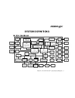
Page 29: ...T1636 15 LCD connector 17 LCD connector SB VIA VT8237R 2 5 HDD in Main Unit IDE1 Connector Ethernet 10 100 MB LAN Chip USB Device USB 0 3 HDD in Base SATAport BIOS LPC I O W83627HG COM2 RS232 Device 5V COM1 RS232 Device 5V USB5 USB Touch controller RS232 IR Touch controller LPT1 Parallel Printer PS 2 KB Port KB LPC I O F81216D COM4 RS232 Device 5V COM3 RS232 Device 5V uDOC USB6 USB4 Proprietary US...

Page 30: ...N ASSIGNMENT OF 4 PIN SOCKET PIN DEFINITION 1 12 V 2 12 V 3 GND 4 GND LAN PORT PIN ASSIGNMENT OF 8 PIN TELEPHONE JACK PIN DEFINITION 1 TD 2 TD 3 RD 4 NC 5 NC 6 RD 7 NC 8 NC This port is defined as 100 base T or 10 base T LAN port This port is utilized by the system in pnp Plug N Play way IRQ assigned is not fixed for this port Most usual observation is IRQ 11 1 3 CASE 2 4 PIN 1 PIN 1 ...

Page 31: ...BLE DB9M RJ45 PIN PIN DEFINITION ALTERNATIVE DEFAULT SETTING 1 1 DCD BATTWK BATTWK 2 2 RX 3 3 TX 4 4 DTR 5 5 GND 6 6 DSR 7 7 RTS 8 8 CTS 9 9 RI 5 VDC RI 10 N C All COM ports appear in form of RJ45 type 10 pin modular connectors like the right drawing However after use of the conversion cable supplied the pin assignment in DB9 connector of the conversion cable complies to RS232 standard IRQ 4 is as...

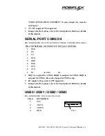
Page 32: ...IN D CONNECTOR OF CONVERSION CABLE PIN DEFINITION ALTERNATIVE DEFAULT SETTING 1 DCD 2 RX 3 TX 4 DTR 5 GND 6 DSR 7 RTS 8 CTS 9 RI 5 VDC RI IRQ 3 is assigned for COM2 IRQ10 is assigned for COM3 IRQ5 is assigned for COM4 All can be changed in CMOS setup DC supply to these ports is UPS supported Jumper selection please refer to the description in Hardware details of this manual USB0 USB1 USB2 USB3 PIN...

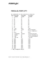
Page 33: ... D3 D3 6 D4 D4 D4 7 D5 D5 D5 8 D6 D6 D6 9 D7 D7 D7 10 ACK INTR ACK 11 BUSY WAIT BUSY PeriphAck 12 PE NU Perror AckReverse 13 SLCT NU SLCT 14 AUTO FEED Datastb AutoFeed HostAck 15 ERROR NU Fault PeriphRequest 16 INIT NU Init ReverseRequest 17 SLCT IN NU SLCT IN 18 GND GND GND 19 GND GND GND 20 GND GND GND 21 GND GND GND 22 GND GND GND 23 GND GND GND 24 GND GND GND 25 GND GND GND IRQ 7 is assigned f...

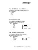
Page 34: ...C 3 GND 4 VCC 5 KBCLK 6 NC SATA CONNECTOR l This connector is a double deck SATA connector PIN ASSIGNMENT OF EACH 7 PIN CONTACTS PIN DEFINITION 1 GND 2 RX 3 RX 4 GND 5 TX 6 TX 7 GND HDD POWER CONNECTOR l This connector is a small 4 pin connector with housing PIN ASSIGNMENT OF 4 PIN CONTACTS PIN DEFINITION 1 GND 2 12 V DC 3 5 VDC 4 GND PIN 1 PIN 1 PIN 1 ...

Page 35: ...al Manual 4 7 AUDIO OUT on side mount kit only PIN ASSIGNMENT OF 3 5 Ø STEREO JACK CONTACT ON PLUG DEFINITION TIP R RING L OUTER GND MIC IN on side mount kit only PIN ASSIGNMENT OF 3 5 Ø MONO JACK CONTACT ON PLUG DEFINITION TIP IN OUTER GND ...

Page 36: ......

Page 37: ...ere No matter what the ventilation of the environment should be much improved to compensate the heat accumulation due to such excessive load COM1 APPLICATION COMMENT Before using the port COM 1 the COM1 terminator should be removed and stored for future use when there will be no regular RS232 device to be connected to this port It is definitely inadvisable to connect any serial input devices like ...

Page 38: ...ination is pressed earlier settings will be renewed to the latest settings PS 2 INTERFACE DEVICE If the KS 6215 6217 series is not installed with any regular PS 2 keyboard nor Posiflex programmable keyboard at system boot up the application of some PS 2 interface device such as a bar code scanner could encounter some trouble if the OS used is Win 2000 The registry modification as hot fix mentioned...

Page 39: ...ase check the BIOS setting accordingly if the configuration has been changed POWER ON OFF CONTROL EXTERNAL POWER SWITCH Whenever the Jiva KS series is to be powered on for the first time after connected to external AC power this switch must be engaged to turn on the power This switch is originally an ON OFF power switch It can be programmed into a power ON only switch through software command To p...

Page 40: ...ff for the sake of system maintenance In that case the programmer has to program the command to close the application programs just like Alt F4 in Windows and then at the end of the closing operation the application program should issue the above mentioned software switch off command string to COM1 under the protocol 9600 bps parity none 8 data bits 1 stop bit FORCED POWER OFF In case of serious s...

Page 41: ... optional UPS battery is a maintenance free lead acid battery and is targeted to support basically the data preservation and smooth running of the system during intermittent power failure This battery is not designed for prolonged power support to the system against power shutdown That means when the AC power outage is known to last for more than few minutes it is advisable to turn off the system ...

Page 42: ...tomatically popping up warning message window to remind the user of a possibly failed battery so that the user won t have to bother checking in the Posiflex Power Switch Manager personally every time Listed below are command code strings to COM1 port under protocol 9600 bps parity none 8 data bits 1 stop bit for reference if the software programmer wants to issue separate commands directly Ÿ To en...

Page 43: ...et to 3F8h 3FFh conventional address for COM1 in system configuration AUTOMATIC POWER ON CONTROL When the system is turned off after a successful boot up the preset automatic power on functions if set as below will keep monitoring for the preset conditions and turn on the system when the preset conditions are met Please note that if the system is improperly turned off before a complete boot up pro...

Page 44: ...ns Now the networking technician at the master machine can execute the same file RSET8139 EXE and select Run Diagnostics à Run Power Management Test à Master Machine à Magic Packet There will popup a dialog box Enter the registered 6 2 digit Ethernet Address of the target machine and press Enter then the target machine of that Ethernet Address will be automatically powered up FINGERPRINT SENSOR Wh...

Page 45: ...CH MANAGER The power switch manager determines the UPS control and function of the hardware power switch that is at side of the machine When the manager program is installed there is an item in the system s Start menu The window display of this program is like the picture at the right POWER SWITCH SETTING The function of the power switch that is in side cover of the machine can be defined here Whe...

Page 46: ...ogrammable between 1 and 255 and each count represents 1 sec delay This software power off command is an irrevocable process just like pulling the plug after a certain delay to allow the shutdown procedures So special care must be exercised in using this software power off command However this command must be engaged to turn the power off when the power switch is set to ON Only POSIFLEX USB MSR MA...

Page 47: ...um approach This means that for example when A is read the scan codes for pressing and holding Alt key while pressing 6 and 5 keys of the numerical keypad consecutively are sent to the keyboard controller Therefore the data will not be misinterpreted regardless of the keyboard layout ENABLE MSR TRACK 1 A tick in the check box enables the reading of track 1 data if the reader head for track 1 exist...

Page 48: ...cessing algorithm and the keyboard data input buffer in an operating system are arranged in such a way that the system resources are preserved as much as possible while data input from the USB keyboard port presents no problem However as we know that the amount of data read from one single swipe of MSR can be very much larger than any possibly fastest keyboard entry in same duration Some operating...

Page 49: ...e Alt Num emulation and the intercharacter delay PROGRAMMABLE KEYPAD When a upgrade kit KP 300 is preinstalled in this system an utility called Posiflex USB Programmable Keyboard will appear in the program group Posiflex Tools of the preloaded OS This utility can be used to define the programmable keys on KP 300 under Windows environment Drivers KP uKBW xxx in Posiflex product information CD is th...

Page 50: ...ar the programmed content of a programmable key Please ignore any gray command relating to Page that is applicable only to other models of Posiflex programmable keyboard and remains here only for consistency consideration Same comment applies to the gray View menu The Config menu determines the keypad beep response and the InterCharacter Delay of the keypad output The MSR menu in the keyboard prog...

Page 51: ... give only the answer back code of the last position of control key when it is turned across multiple positions or when the keyboard receives an Enquiry command from the host system POSIFLEX USB TOUCH MANAGER When the touch control panel installed is the resistive type panel and the touch control interface used is USB interface the Posiflex USB Touch Manager will be installed with the preloaded OS...

Page 52: ...esults in unsatisfactory touch accuracy l Reset To Default This button resets all touch parameters l Enable PIR This check box is not applicable to the monitor Please keep it unchecked l Enable Touch This check box must be checked to have the touch panel working l Touch as Right Button Click This check box defines each touch on touch panel as clicking the right button of mouse at that point When i...

Page 53: ...rgin This list button selects the range to engage edge acceleration toward the edge before the edge is reached l Compensation This list button selects the distance to advance the mouse toward edge from touch point USB TOUCH RIGHT BUTTON TOOL This tool differs slightly from the Touch as Right Button Click check box in the USB touch manager When executed there will be a small window of One Shot Righ...

Page 54: ... the Posiflex Product Information CD and study the readme file before executing the setup program should there be any need for a driver re installation Make sure you select COM2 for the port of the touch driver in the process All control parameters of this driver can be reviewed through an item Elo Touchscreen in the Control Panel after driver installation Some sample screen shots of this driver a...

Page 55: ...icking would become very difficult because the 2 touches would be considered at 2 different spots The port selection for Touchscreen on must be set to COM5 for the touch panel over the LCD panel in this product series In case a Posiflex touch monitor is connected to the VGA port for 2nd display the touch function of the second display monitor has to be connected to one of the ports from COM2 to CO...

Page 56: ... External Power Switch Main switch ON OFF 5 3 Application Guide Power On Off Control External Power Switch Software power off 5 4 Application Guide Power On Off Control Software Switch Off Enhance forced power off 5 4 Application Guide Forced Power Off Enable UPS function 5 6 Application Guide UPS Function Enabling Disable UPS function 5 6 Application Guide UPS Function Enabling Check battery dete...

Page 57: ...ear a corner of a jumper with 2 rows of pins is used to indicate the position of pin number 2 for identification of all pins CN11 2 2 1 JP3 JP10 2 JP2 1 JP4 1 JP8 JP9 CN7 LPT1 VGA1 LAN1 LCD2 2 IDE1 2 LCD1 2 U13 U16 U42 Y2 X3 F10 F8 F13 F9 F7 CN15 1 2 JP25 1 JP9 CN24 1 J6 1 COM1 COM2 F12 COM3 COM4 CN27 JP24 2 1 X2 X1 Y1 F2 CN23 1 VR1 SW1 CN25 SPK1 BAT2 CN14 CN13 CN1 BAT1 BZ1 CN22 2 U24 U20 Y5 Y4 F4...

Page 58: ...used to indicate the position of pin number 1 2 A small number 2 marked near a corner of a jumper with 2 rows of pins is used to indicate the position of pin number 2 for identification of all pins SODIMM1 1 U7 U9 F14 U8 Service window details JP12 JP10 JP21 2 J5 2 JP17 2 JP20 2 JP11 2 JP13 The orientation of JP13 above is for rev C only In rev D it is as below JP13 ...

Page 59: ...N24 HDR 1x5 w H mini LED light panel connector CN25 mini DIN 6 Jack PS 2 KB port CN27 2x SATA Jack SATA ports COM1 10 pin RJ45 jack COM1 port COM2 10 pin RJ45 jack COM2 port COM3 10 pin RJ45 jack COM3 port COM4 10 pin RJ45 jack COM4 port F1 SMD fuse Fuse for 5V power in USB ports F2 Poly fuse Fuse for 12V power in VGA port F3 SMD fuse Fuse for 5V power in USB ports F4 SMD fuse Fuse for 5V power in...

Page 60: ...witch Power switch VGA1 DB3x5 F VGA port VR1 Thumb wheel VR LCD brightness control U13 IC LAN chip U16 IC BIOS U20 IC Power manager U24 IC LPCIO 1 U39 IC LPCIO 2 U42 IC LVDS transmitter U43 IC CODEC ON SOLDER SIDE Position Part Spec Usage F14 SMD fuse Fuse for PS 2 KB port 5V 1 1A J5 HDR 2x4 USB touch setup JP10 HDR 1x3 CMOS data control JP12 HDR 1x2 VGA 12V DC supply select JP11 HDR 2x3 COM1 COM2...

Page 61: ... SUPPLY SELECT STATUS OF JP11 ON SOLDER SIDE PIN 9 STATUS 1 3 short COM1 Pin9 connected to 5 V DC 3 5 short COM1 Pin9 connected as RI 2 4 short COM2 Pin9 connected to 5 V DC 4 6 short COM2 Pin9 connected as RI COM3 COM4 DC SUPPLY SELECT STATUS OF JP20 ON SOLDER SIDE PIN 9 STATUS 1 3 short COM1 Pin9 connected to 5 V DC 3 5 short COM1 Pin9 connected as RI 2 4 short COM2 Pin9 connected to 5 V DC 4 6 ...

Page 62: ...er is present The user has to change this jumper if he she wants to detect the standard DCD signal on COM1 USB TOUCH SETUP STATUS OF J5 ON SOLDER SIDE APPLICABLE OS 1 2 short 5 6 open Windows Win98 Win2000 WinXP 1 2 open 5 6 open Linux or WinCE 1 2 short 5 6 short MS DOS 3 4 short Touch panel type E or OEM panel 3 4 open Touch panel type F Please note for MS DOS application of the USB touch the US...

Page 63: ... 7 uDOC HOLD STATUS OF JP19 uDOC STATUS 1 2 4 5 Short No uDOC installed Connected to J100 of uDOC When uDOC installed PS 2 MOUSE SIGNAL LOOP STATUS OF JP25 PS 2 MOUSE SIGNAL 1 2 3 4 Short No PS 2 touch controller All open Through PS 2 touch controller ...

Page 64: ...PONENT SIDE SOLDER SIDE CONNECTORS ON COMPONENT SIDE Position Part Spec Usage J2 FPC connector To IR touch control panel ON SOLDER SIDE Position Part Spec Usage J1 Connector 2x8 To RS232 IR touch connector CN22 on main board J3 Connector 2x4 To JP25 on main board Y2 Y1 1 J2 U3 U7 2 J1 J3 2 ...

Page 65: ...6217 series Technical Manual 6 9 uDOC CARD COMPONENT SIDE SOLDER SIDE CONNECTORS ON COMPONENT SIDE Position Part Spec Usage J100 HDR 1 x 5 To JP19 on main board J101 HDR 2 x 5 To JP14 on main board 1 U10 J100 J101 2 U2 U1 ...

Reviews: