KS-6215 / KS-6215I / KS-6217 series Technical Manual 5 - 1
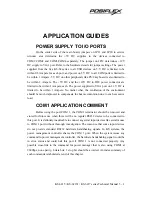
APPLICATION GUIDES
POWER SUPPLY TO I/O PORTS
On the solder side of the main board, jumpers on JP11 and JP20 in service
window area determine the +5V DC supplies to the devices connected to
COM1/COM2 and COM3/COM4 separately. The jumper on
JP12 dete12V
DC supply to VGA port. Refer to the hardware details for jumper settings. The power
supplied from the Jiva KS-62 series to all USB devices on 5 V DC is limited to be
within 0.5 Ampere for each port, and power on 5 V DC to all COM ports is limited to
be within 1 Ampere. 5 V DC on other peripherals like PS/2 keyboard is also limited to
be within 1 Ampere. The +5V DC and the +12V DC in IDE power connector are
limited to be within 1 Ampere each. The power supplied to VGA port on 12 V DC is
limited to be within 1 Ampere. No matter what, the ventilation of the environment
should be much improved to compensate the heat accumulation due to such excessive
load.
COM1 APPLICATION COMMENT
Before using the port COM 1, the COM1 terminator should be removed and
stored for future use when there will be no regular RS232 device to be connected to
this port. It is definitely inadvisable to connect any serial input devices like serial mouse
to COM 1 port without thorough investigation. The reason is that some input devices
do not provide standard RS232 hardware handshaking signals. In KS systems, the
power management controller shares the COM 1 port. When the system issues any
command to power management controller, the hardware handshaking signal would be
in error status and could halt this port if COM 1 is not connected properly. Any
possible cross-link to the command for power manager that is also using COM1 at
9600bps, none parity, 8 data bits, 1 stop bit should be avoided. An index summary of
such commands is tabulated at end of this chapter.
Summary of Contents for Jiva KS-6215 Series
Page 16: ...KS 6215 KS 6215I KS 6217 series Technical Manual 2 4 ...
Page 36: ......


