background image


1.  The KB2100 and the PS/2 computer keyboard can be attached to the 

computer without a selection switch. To implement, connect the KB2100 
to the computer as outlined above. Plug the PS/2 computer keyboard into 
J1 of the KB2100. 

Note:

 KB2100 connectors J5 and J6 are not used.


C.  KB2100-R, and a Computer terminal: 

1.  Connect J6 of the Kb2100-R to a RS232 port of the computer terminal. 

Note: 

J1, J2 and J5 are not used.


FUNCTIONAL TEST 

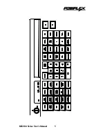
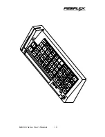
To determine the proper working condition of the KB2100, a test key 

pattern was preprogrammed into the keyboard memory. Page 5 shows this test 
pattern. For a quick functional test follow the functional test procedure below: 

1. 

Connect the KB2100 as shown in the section “Connecting the KB2100 to 
the Computer”. 

2. 

Turn on the computer. 

3. 

At the DOS prompt press the upper left-hand key on the keyboard. 

4. 

If the word “PRICE” appears on the screen, the KB2100 is working! 

5. 

To check all 55 keys, press each individual key and compare the result 
with the test pattern. 

6. 

To check out the magnetic stripe reader: 
Hold a credit card with the magnetic stripe at the bottom and facing the 
arrow mark. Slide the card through the reader slot. Make sure the bottom 
edge of the card continuously touches the bottom edge of the reader. The 
recorded data from the credit card will appear on the monitor. 

KB2100 Series User’s Manual 

Summary of Contents for KB2100 SERIES

Page 1: ...KB2100 SERIES 55 PROGRAMMABLE KEYBOARD USER S MANUAL Rev C ...

Page 2: ...OTICE This equipment generates uses and radiate radio frequency energy If not installed and used in accordance with the user s guide may be cause interference to radio communications It has been tested and found to comply with limits for a Class A digital device pursuant to subpart J of Part 15 of FCC Rules which are designed to provide reasonable protection against interference when operated in a...

Page 3: ... CONTENTS FEATURES 1 CONTENTS OF CARTON 2 CONNECTING THE KB2100 TO THE COMPUTER 3 FUNCTIONAL TEST 4 PROGRAMMING THE KB2100 6 COMMAND MENU 8 ADVANCED PROGRAMMING 10 SPECIAL CONFIGURATION 12 SPECIFICAITONS 16 ii ...

Page 4: ...onal output formats Standard keyboard emulation and RS232 Features an optional magnetic stripe reader KB2100M2 Capable of reading tracks 1 2 and both tracks 1 2 KB2100M3 Any combination of tracks 1 2 and 3 Built in decoder and wedge interface Permits simple field programmability Supports down loading of an entire 55 key template into the internal non volatile memory in just 7 seconds Includes repl...

Page 5: ...CONTENTS OF CARTON 1 POS Keyboard 2 Keyboard to Computer interface cable 3 Utility software disk 4 Three legend label sheets 5 User s Guide 6 Key clip KB2100 Series User s Manual 2 ...

Page 6: ...standard computer keyboard can be attached to the computer without a selection switch To implement connect the KB2100 to the computer as outlined above Plug the standard computer keyboard into J5 of the KB2100 Note KB2100 connectors J1 and J6 are not used B Connecting the KB2100 to a PS 2 Computer KB2100 as a stand alone keyboard 1 Using the supplied interface cable connect the KB2100 to the compu...

Page 7: ...st pattern For a quick functional test follow the functional test procedure below 1 Connect the KB2100 as shown in the section Connecting the KB2100 to the Computer 2 Turn on the computer 3 At the DOS prompt press the upper left hand key on the keyboard 4 If the word PRICE appears on the screen the KB2100 is working 5 To check all 55 keys press each individual key and compare the result with the t...

Page 8: ...KB2100 Series User s Manual 5 KB2100 Series User s Manual 5 ...

Page 9: ... until all keys required are programmed It is not necessary to program all the keys for the KB2100 to function properly The maximum number of characters per key is 255 and the maximum number of characters for all 55 keys is 1856 5 Programming locations A1 and B1 are associated with lock key switch Usually the lock key is controlled by management level personnel to override certain security check o...

Page 10: ...top 10 For direct transfer between a template file and the KB2100 there is a shortcut program named RWM EXE The command RWM filename tpl transfers from file in hard disk to data in the KB2100 non volatile memory and the command RWM filename tpl R transfers from data in the KB2100 non volatile memory to file on the hard disk KB2100 Series User s Manual 7 ...

Page 11: ...ALT S Delete contents of a key to the buffer DEL COPY contents of a key to the buffer ALT C PASTE contents of a key from the buffer ALT P UNDO the change made to a key ALT U Input a MULTI LEVEL SHIET mark ALT M Change the keyboard CONFIGURATIONS ALT G or F3 Note The commands marked with do not apply to model KB2100 series W R L S HDRD DISK KB 2100 RAM The KB2100 keyboard working in conjunction wit...

Page 12: ... s volatile RAM memory The same template can then be written W into the non volatile memory of the KB2100 This process as an example allows a restaurant to change a breakfast menu to a lunch menu in just seven seconds Read R a working KB2100 template into the computer s volatile RAM memory The template can then be saved S to the hard disk for future use KB2100 Series User s Manual 9 ...

Page 13: ... ESC key press ESC twice See special notes below 3 When use of any of ALT CTRL or SHIFT in a programmed key causes any trouble in the application please program a release code of the above three keys in proper sequence to get smooth operation Procedure is as the following For example to program the ALT D key 1 Press F8 to Enter scan code mode 2 Press ESC ALT D 3 Press ESC F ESC ALT to release the ...

Page 14: ...r key programmed as the change Level key for the multi level programmed key to works Select an empty key to be used as the change Level key Press ALT and M together to put a level marker m to the content of the key To put two level markers m m to the change Level Key just press ALT and M together twice Any Change Level Key Programmed with more than 7 level markers will be regarded as with only 7 l...

Page 15: ...Lock function to the keypad 1 Start the KBM EXE utility program 2 Select the key which will become the Cap Lock key Press ALT A to enter the ASCII code mode 3 Press ALT and C together SPECIAL CONFIGURATION Special configuration is accessed through F3 for the configuration menu The following options are available a Send Break Codes for Scan Code YES b Beep while a key is pressed YES c Beep if a key...

Page 16: ...cally So that unless there is any release code programmed the SHIFT CRTL ALT key if programmed in a Scan Code edited key will remain pressed at the end of that Scan Code edited key The default of this item is YES b Beep while a key pressed When this item is set to YES the programmable keyboard is enabled to deliver a beeping sound for the key press operation When this item is set to NO the program...

Page 17: ...characters when the key is pressed is adjustable to match the system requirement The time delay in transmitting two adjacent characters defined in a programmed key when that key is pressed is hereby defined as interchatacter delay and is adjustable between 0 and 140 milliseconds Press j to increase or press k to decrease by one millisecond each time till suitable delay time is reached The default ...

Page 18: ...EN which means that one bit is engaged for even parity check Further press of n key will change this item to ODD which means that one bit is engaged for odd parity check One more press of n key will return the choice to NONE again o Data bits This item is also used in model KB2100R only and will show up and be effective only when the RS232 output is enabled item l set to YES The default value for ...

Page 19: ...32 to 122 ºF Storage temperature 20 to 70ºC or 4 to 168ºF Relative humidity 90 non condensing Vibration 4G Shock 40G ELECTRICAL Voltage 5VDC 10 Current 25 ma 50 ma Models KB2100M2 M3 R MAGNETIC STRIPE READER Models KB2100M2 M3 Tracks 1 2 and 3 Card feed speed 4 to 47 inches second Card feed force 6 oz typical Head life 300 000 passes minimum KB2100 Series User s Manual 16 ...

Page 20: ... 2 1 J2 1 Clock J2 2 Keyboard data J2 3 NC J2 4 Ground J5 J2 5 5VDC 5 4 2 1 3 J5 1 Clock J5 2 Keyboard J5 3 NC J6 J5 4 Ground 5 4 3 2 1 J5 5 5VDC Model KB2100 R J6 1 4 6 DCD DTR DSR 8 9 7 6 J6 2 Jumper selectable as output J6 3 Jumper selectable as output J6 5 Ground J6 7 8 RTS CTS J6 9 5VDC KB2100 Series User s Manual 17 ...

Page 21: ...KB2100 Series User s Manual 18 ...

Page 22: ...KB2100 Series User s Manual 19 ...

Reviews: