Part 10
pay particular attention to the environment requirements for UPS battery in
next chapter “USING THE TOUCH POS”.
BASE MOUNT UPGRADE KIT
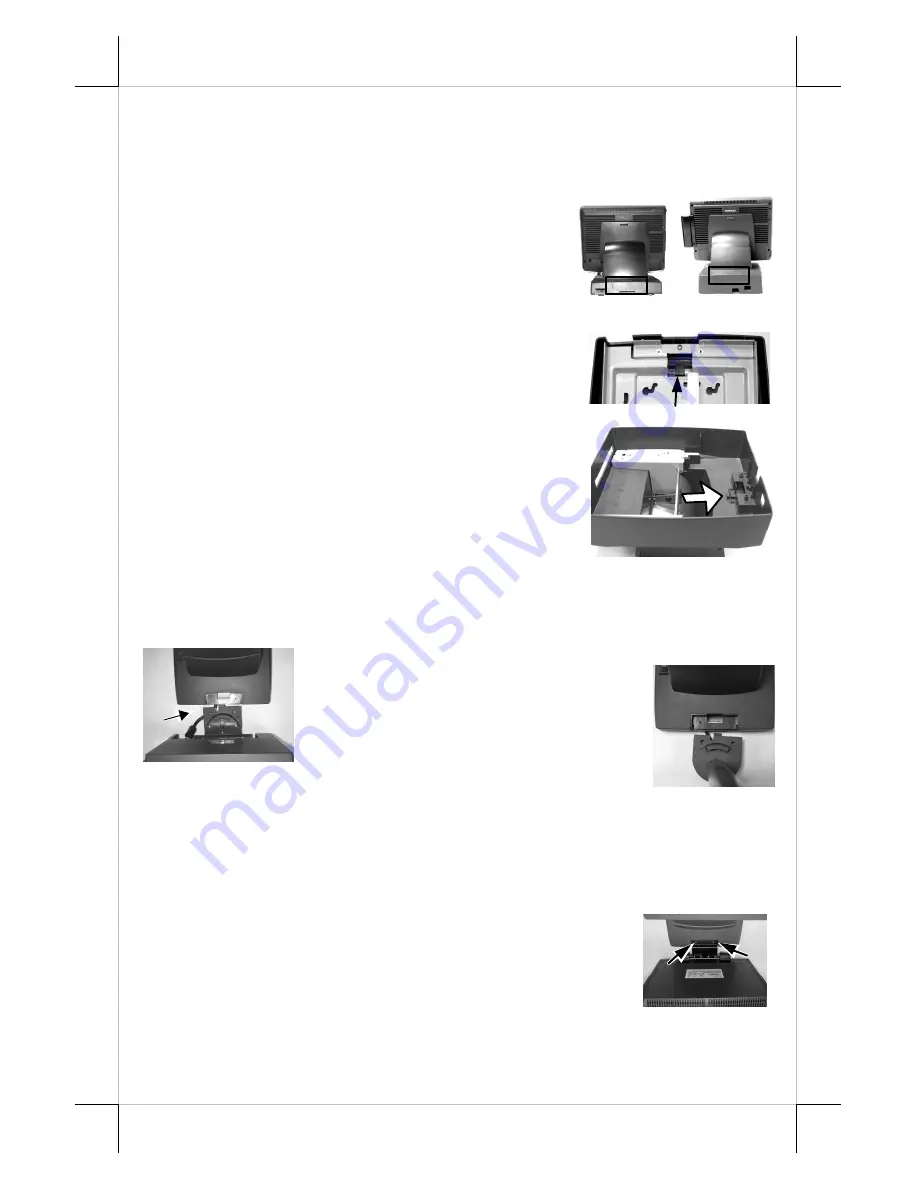
On rear edge of the stand assembly for
desktop mount application, there is a rear connect
cover. Either a 2nd LCD display panel option LM-
6201 or a VFD customer display option PD-2501
can be installed here after removing this cover.
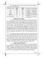
To remove the rear connect cover in slim base please refer to the
inside view of the base unit at right and use a flat
head screwdriver to pick the plastic hook plate of the
rear connect cover from inside behind the UPS
battery.
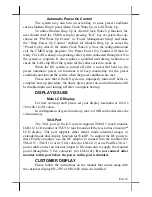
The rear connect cover of universal base can
be removed by pushing the plastic hook plate of it
from inside as marked by white arrow in the right
picture. However, this picture is an up-side-down
inside view of the stand assembly with base box
removed for illustration purpose only. Please push the
plastic hook plate with finger through the top opening
in the stand assembly to remove the rear connect cover.
12” 2
nd
LCD Panel Or Customer Display
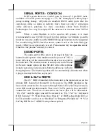
Fit the joint base of PD-2501 or PD-2602 or
LM-6101 to the rear connect cover
opening. Please route the interface cable
through the normal cable exit (under the
joint base) as in the 2 pictures. Fit 2
screws
through washers
to hold the
joint tight. For low profile customer display PD-305, the
installation procedure is same. Remember to enable the +5 V DC supply in the
COM port of the main unit for PD-2501, PD-2602 or PD-305 or the +12 V DC
in VGA port for LM-6101.
15” 2
nd
LCD Panel
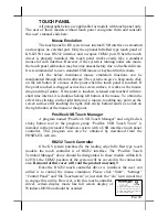
A bracket kit including a steel interface bracket
will be provided with the 15” 2
nd
LCD panel LM-6301.
Please follow the accompanying installation guide to mount
the interface bracket and fix it to the rear connect area of the
system as in the right picture. Route the VGA through the
cable exit of the base stand to the main unit. Connect the attached power
adaptor for its power source.


