background image


Part 17 

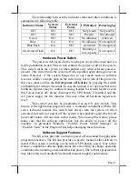
The relationship between the indicator status and other conditions is 

summarized in following table: 

Indicator Status 

System 

Status 

External 

Power 

UPS Battery  Powering Up 

Off 

Off 

Off 

Not present  Not possible 

Off 

Off 

Off 

Present 

Not allowed 

Green 

Off 

On 

No influence 

Allowed 

Blue 

On 

On 

No influence  Not required 

Blue/flash 

On 

Off 

Activated 

Not required 

Green/rapid flash 

On 

Off 

Running at 

low capacity 

Not required 

Hardware Power Switch 

The power switch located in the touch open cover of the main unit is a 

tactile pushbutton switch. This switch controls the power on/off of the system. 
This switch turns the system on when pushed only when external power is 
present. This switch turns the system off when pushed again during power on 
status. However, if the system hangs due to any reason such as software 
resource conflict a simple push on the switch may fail to turn off the power. In 

this case, please utilize the 

forced power off feature

 by pressing the switch 

and holding for within 10 seconds. In case the turmoil is so vigorous that some 
hardware registers may be confused causing trouble for system restart or even 
this forced power off, please disconnect the UPS battery if installed and the 
AC power supply for few minutes. This may allow all hardware registers to 
reset. 

This switch can also be programmed as an ON only switch. That 

means, if the application program issues a  command compliant with the KS 
series technical manual, this switch will always turn the system on when 
activated, but will not power off the system when pushed again (the forced 
power off feature will not work in this mode). When using this feature, please 
make sure that the software application has the ability to power off the 
machine. In preloaded Windows, “Posiflex Power Switch Manager” in 
“Posiflex Tools” in the Program Files helps managing these functions. 

Software Support Features 

The KS series provides a software power off command for application 

program maneuvers. The KS also provides a specific means for the software to 
detect if the system is working on external or UPS battery power. Due to this 
feature, compatible software applications have the ability to change operating 
conditions when running on standard/backup power. The software programmer 
may take reference from the KS technical manual to apply such features. 


Summary of Contents for KS - 6215N

Page 1: ...esulting from the furnishing performance or use of this material This information is provided as is and Posiflex Technologies Inc expressly disclaims any warranties expressed implied or statutory including without limitation implied warranties of merchantability or fitness for particular purpose good title and against infringement The information in this manual contains only essential hardware con...

Page 2: ...improper maintenance reduces the battery life dramatically Always fully recharge the battery at least once every 3 months if the battery is not connected Always disconnect the UPS battery from the system if the system is to be left OFF for more than 72 hours to prevent possible damage Only connect the UPS battery back right before you are going to re power on the system Replace the battery as soon...

Page 3: ...NTRODUCTION PRODUCT PICTURES Front Views Side Views 1 1 11 12 Slim base Universal Base 10 10 9 9 6 5 Slim base 13 14 15 6 1 Slim base 6 3 4 1 1 Universal Base Slim base Universal Base 4 5 6 8 7 7 8 9 9 6 5 2 2 ...

Page 4: ... Removal hollow in cable cover 9 Lock release lever for tilt angle adjust 10 Lock release button for main unit detach 11 Touch open cover 12 Power switch 13 Brightness adjust thumb wheel 14 Touch open door latch 15 PS 2 KB port 16 Rear connect cover 17 Power connector hole 18 Cable exit 19 2nd Cable exit 18 Universal Base 21 Slim base 18 19 20 21 1 1 Slim base Universal Base 7 7 6 5 18 18 16 16 17...

Page 5: ...port WinCE Win XP Pro WEPOS POS Ready and Linux environment f High quality 15 TFT active matrix LCD panel g Brightness control by either software or hardware h Vertical type LCD panel with easy tilt angle adjustment from 15 to 70 i Durable resistive type leading edge Infra Red type optional touch panel that endures 35 million touches min at same spot j Spill proof water resistant structure allowin...

Page 6: ...t MODEM ring or LAN Option Items Note The underlined items in the following list means that option must be set prior to shipment from the factory The rest items can be set by the dealers a DDR2 SDRAM memory expansion up to 1GB b RS232 interface Infra Red type touch panel durable for 50 million touches min at same spot c 2 HDD installation or uDOC d Integrated side mount upgrade kit SD400 MSR finge...

Page 7: ...ible then Please first note orientations of every existing cable connection and then disconnect every cable properly before separating the main unit from the adjustable stand assembly Please note that the click lock spring has to be pressed down prior to pulling out the connector such as the LAN port Please also note that the fixing screws have to be loosened free prior to disconnection such as th...

Page 8: ...om plate up and the inside of an example slim base model looks like this in the above right picture The inside of an example universal base model will look like the picture on next page Both with numbered items listed on next page However there could be some variation to the contents inside depending on what option items actually installed Step A Prepare a soft clean flat surface such as a piece o...

Page 9: ...through the 2 standing slits on base box to fix the battery in position firmly Route the battery connection cable through appropriate passage to the battery connector on the main unit Please remove the UPS battery bracket fixing screw and slide right the UPS battery bracket to take it out for universal base model as in left picture Put the battery in at the other end first and remount the bracket ...

Page 10: ...or illustration purpose only Please push the plastic hook plate with finger through the top opening in the stand assembly to remove the rear connect cover 12 2nd LCD Panel Or Customer Display Fit the joint base of PD 2501 or PD 2602 or LM 6101 to the rear connect cover opening Please route the interface cable through the normal cable exit under the joint base as in the 2 pictures Fit 2 screws thro...

Page 11: ...ort and COM port power supply function Please consult your dealer for technical support on setup of these jumpers Please note that only those qualified technicians may adjust in the service window with information from Posiflex and the contents in the service window may change without notice as time develops SIDE MOUNT UPGRADE KIT Remove the 2 circled screws in last picture above to remove the cov...

Page 12: ...ed type touch panel is used KS 6115U 294 5 391 5 WALL MOUNTING The wall mount model is delivered without any base but with a wall mount kit Please follow the installation guide that comes with the wall mount bracket to fix the wall mount bracket on wall and then hang the main unit with the matching pegs into the matching holes on wall mount bracket Please note that since there is no base for the w...

Page 13: ... care of software restoration after OS recovered A Posiflex supplied USB interface CDROM drive will be required for such action Other brand CDROM drive may require its specific driver different from what supported in the recovery CD Should there be any difficulty in using the Posiflex supplied USB interface CDROM drive in recovery please try disable the USB 2 0 function of system BIOS setup by goi...

Page 14: ...Part 14 Inc shall not be responsible for any technical support to questions arisen due to non preloaded OS ...

Page 15: ... hours every month for temperature over 30 C Temperature above 40 C must be strictly avoided as it could cause termination of battery life and unexpected result even if the battery is not in work The UPS battery can support basically the data preservation and smooth running of the system during intermittent or few minutes 15 30 min depending on loading and battery condition power failure Battery r...

Page 16: ... power outlet and any power fusing arrangements must conform to local safety regulations Please never do any connection disconnection when system is still powered on Please always keep the external power adaptor in a free air circulation POWER ON OFF Touch Open Cover A gentle tap on the touch open cover at left side of the main unit will open the cover and show the power switch thumb wheel knob fo...

Page 17: ...re registers may be confused causing trouble for system restart or even this forced power off please disconnect the UPS battery if installed and the AC power supply for few minutes This may allow all hardware registers to reset This switch can also be programmed as an ON only switch That means if the application program issues a command compliant with the KS series technical manual this switch wil...

Page 18: ...et Please note that if the KS system is improperly turned off before a complete boot up procedure the above preset power on control functions will be disabled until next turning off after a complete boot up DISPLAY ISSUES Main LCD Display For best viewing result please set your display resolution at 1024 x 768 with 16 2 M colors In configuration of system memory max 64 MB can be shared as the vide...

Page 19: ...rner of the main unit but no direct access port in the main unit The external access to audio ports can be found in the side mount option kit like SD 400 with a Microphone in and a stereo line out jacks at its bottom surface as circled in the right picture The internal speaker will be automatically disconnected when a plug is inserted in the line output jack HDD SATA PORTS The 2 5 HDD if installed...

Page 20: ...f the mouse To obtain the effect like clicking on the right button of a mouse touching any point on the screen surface after touching the right click sticky button results as a click on the right button of the mouse at that point Posiflex USB Touch Manager A program named Posiflex USB Touch Manager and a right click sticky button tool in the program group Posiflex USB Touch Tools is installed in t...

Reviews: