PST-6000 series Technical Manual 4 - 4
TM
•
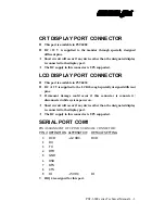
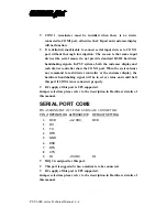
COM 1 terminator must be installed when there is no device
connected to COM1 port, otherwise the CR port and customer display
will not function.
•
It is definitely inadvisable to connect serial input devices to COM 1
port without thorough investigation. The reason is that some input
devices like serial mouse do not provide standard RS232 hardware
handshaking signals. In PST systems, both the customer display and
cash drawer controller share the COM 1 port. When the system issues
any command to cash drawer controller or the customer display, the
hardware handshaking signal will be in error status and could halt
this port if COM1 is not connected properly.
•
DC supply of this port is UPS supported.
Jumper selection: please refer to the description in Hardware details of
this manual.
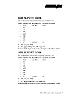
SERIAL PORT COM2
PIN ASSIGNMENT OF 9 PIN D SUB MALE CONNECTOR:
PIN # DEFINITION ALTERNATIVE
DEFAULT SETTING
1
DCD
+12 VDC
DCD
2
RX
3
TX
4
DTR
5
GND
6
DSR
7
RTS
8
CTS
9
RI
+5 VDC
RI
•
IRQ 3 is assigned for this port.
•
This port is suggested when a modem is to be connected.
•
DC supply of this port is UPS supported.
Jumper selection: please refer to the description in Hardware details of
this manual.
Summary of Contents for PST-6000 SERIES
Page 1: ...TM Rev A L 1 L 0 L P L 2 L 3 L 4 L 1 L 0 L P L 2 L 3 L 4 PST 6000 SERIES TECHNICAL MANUAL ...
Page 8: ...vi TM ...
Page 20: ...PST 6000 series Technical Manual 2 10 TM ...
Page 22: ...PST 6000 series Technical Manual 3 2 TM ...
Page 58: ...PST 6000 series Technical Manual 5 28 TM ...
Page 73: ...PST 6000 series Technical Manual 7 3 TM DWG 2 Unscrew the bottom ...
Page 77: ...PST 6000 series Technical Manual 7 7 TM DWG 7 Cable connections inside PST system ...
Page 82: ...PST 6000 series Technical Manual 7 12 TM ASSEMBLY DRAWING ...


