PST-6000 series Technical Manual 7 - 1
TM
SERVICE AND SPARE PARTS
SERVICE GUIDE
OPENING THE KEYBOARD
Whenever there comes to a need for service or maintenance or upgrading,
there may be the need for opening the PST system and having an access to the interior
of the cabinet. The method to access the interior of a PST system can be divided into
following steps: removing the exterior peripherals, opening the programmable
keyboard, detaching the rear cabinet and dissociating the required parts/module from
the chassis.
The possible exterior peripherals attached to the PST system may include
external KB wedge device, printer, CRT or LCD display, VFD customer display and
some devices connected to the I/O ports of PST system such as cash drawers, laser
scanning devices etc..
Before breaking or making any connection or opening any device or the PST
system, please always make certain that all the power for each and every device
involved are turned off and the power cords are removed.
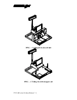
Should there be any device connected to the area inside the front door such as
a KB wedge device or a PC keyboard, all these devices should be disconnected from
the PST system first. Use the mechanical key to open the front door (see DWG.-1). If
this key is lost somehow, the user should request for replacement of the same code of
the mechanical lock. The numerical code of the mechanical lock is printed on a label
stuck at the bottom side of PST near the front door area. The user should provide this
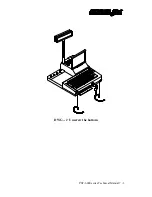
number to get a right key. Unscrew two screws at the bottom side of PST near the
front bottom corners (see DWG.-2) and the user may now lift the programmable
keyboard unit by the front bottom edge of the keyboard unit as shown in the following
drawing DWG.-3 on page 7 - 4.
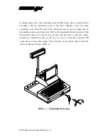
There are three cables to be disconnected from the keyboard unit before the
unit can be completely taken away from the major part of PST system. The user
should disconnect the cable coming from the external keyboard connector or through
Summary of Contents for PST-6000 SERIES
Page 1: ...TM Rev A L 1 L 0 L P L 2 L 3 L 4 L 1 L 0 L P L 2 L 3 L 4 PST 6000 SERIES TECHNICAL MANUAL ...
Page 8: ...vi TM ...
Page 20: ...PST 6000 series Technical Manual 2 10 TM ...
Page 22: ...PST 6000 series Technical Manual 3 2 TM ...
Page 58: ...PST 6000 series Technical Manual 5 28 TM ...
Page 73: ...PST 6000 series Technical Manual 7 3 TM DWG 2 Unscrew the bottom ...
Page 77: ...PST 6000 series Technical Manual 7 7 TM DWG 7 Cable connections inside PST system ...
Page 82: ...PST 6000 series Technical Manual 7 12 TM ASSEMBLY DRAWING ...


