19
Description
Table 3: Power Supply/Battery Back-up Terminal Block pinout
Terminal Block Pin
Function
0 V
Positive voltage to/from battery back-up or redundant power supply Chassis
-24 V
Negative of 24 V to/from battery back-up or redundant power supply
Chassis
-48 V
Negative of 48 V from battery back-up or redundant power supply Chassis
CHRG
Negative of 48 V to battery back-up Chassis
2.2.5
Ground jumper setting
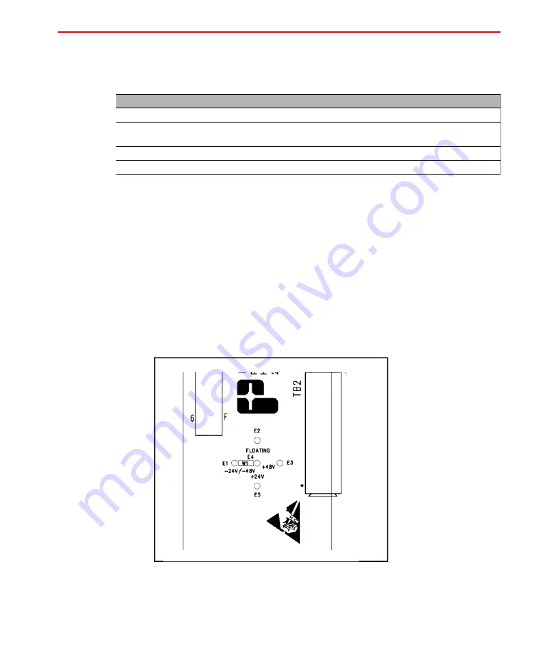
The backplane of the Wall-Mount Chassis is equipped with a jumper setting, W1,
that allows the output to be configured as floating, negative voltage or positive
voltage referenced to ground. The unit is set at the factory to provide negative
voltages (-24 Vdc/-48 Vdc) for Teleline/TeleLite installations.
The configurations are well indicated on the backplane at the different locations
where W1 can be installed.
Q
For a view of the jumper W1, see Figure 3 on page 19.
Figure 3: Ground Jumper (W1)
Summary of Contents for Teleline 750003
Page 2: ......
Page 5: ...Chapter 1 General Information...
Page 12: ......
Page 13: ...Chapter 2 Overview...
Page 15: ...15 Introduction Figure 1 Wall Mount Chassis Q The fuse is a FAST 5A 125V 3AG type fuse NOTE...
Page 17: ...17 Description Figure 2 Wall Mount Chassis Terminal Block View...
Page 21: ...Chapter 3 Installation...
Page 28: ...28 Wall Mount Power Supply Chassis model 750003 Figure 6 Redundant 24 V Power Supply...
Page 29: ...29 Chassis Wiring Figure 7 Redundant 48 V Power Supply...
Page 31: ...31 Chassis Wiring Figure 8 24 V Chassis with Battery Backup...
Page 33: ...Appendix A Acronyms...


