5401587 - REV B • 6/21
PAGE 4 OF 10
Potter Electric Signal Company, LLC • St. Louis, MO • Phone: 800-325-3936 • www.pottersignal.com
SignaLink
™
Bridge
Wireless Supervisory System
WRX-R - Receiver
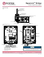
The Receiver provides a dry contact output allowing it to be monitored by any zone or monitor module of any fire panel as just a dry contact input.
The Receiver follows the status of the transmitter so it does not have to be manually reset after activation. When the device connected to the transmitter
restores to normal, the transmitter will send a restoral signal to the receiver causing it to restore to normal.
The Receiver provides three terminals for connection to the FACP, see fig 2. Connect the EOLR from the FACP across the COM and EOLR terminals.
Connect the zone from the FACP across the COM and NO terminals. The EOLR and NO terminals are connected internally by a failsafe relay contact
that is normally energized closed. In the event of a trouble signal from the transmitter or repeater, loss of communication or loss of power to the
Receiver, that relay will drop out and initiate a trouble at the FACP. An alarm or supervisory signal from the transmitter will result in a relay closing
across the COM and NO terminals initiating an alarm or supervisory condition on the FACP depending how the panel is programmed.
Devices do not need to be re-paired when batteries are replaced or if the unit is powered down.
If a WR must be replaced, the wireless Setup tool must be used to remove the MAC address of the old device from the system. Then the new device
can be paired using either the Setup tool or the cover tamper switch.
WTX-M - Transmitter
The Transmitter is designed to be connected to any product not classified as explosion proof that provides a dry contact output. Remove the locknut
from the threaded nipple of the Transmitter, make sure the O ring is properly installed on the nipple and insert the nipple through the ½” conduit opening
of the device. Install the locking nut on the inside of the device and tighten firmly in place.
Connect the two wire leads of the Transmitter and the supplied 5.1k ohm End of Line Resistor across the normally open contacts of the device to be
monitored. Polarity is not a concern.
Installation
Maximum line of site communication is approximately 800 feet between devices. Metal objects can greatly reduce signal strength. A chain link
fence can almost completely block a signal if the fence is too close to the transmitter, repeater or receiver. Metal shelving, walls with metal framing,
metal doors, windows with wired glass, vehicles, all have an effect on the ability of the wireless signal to pass through.
For best transmission/reception of wireless communication, it may help to attempt to install the Transmitter in a position so that it is not completely
obstructed from metal. Rotating the Transmitter enclosure so that it can “see” around the metal Potter device, pipe, valve, etc. may help communication.
When mounting the repeater to a post, it may be necessary to rotate the Repeater on the post to achieve best signal reception/transmission.
Installation shall be performed by qualified personnel and in accordance with all local and national codes and ordinances and the approval of the local
AHJ.
CAUTION
Wireless devices shall not be used as the primary initiating device to activate water or agent suppression systems. Wireless devices may experience
communication or interference issues which could result in an unintended discharge or a failure to discharge.
•
The receiver needs to be connected to a latching trouble zone and re-sound every 4 hours (if silenced). The receiver cannot be monitored by
a zone that uses alarm verification.
•
The receiver shall be mounted adjacent to the fire panel.


