2.0 General Layout
8
© Baxi Heating UK Ltd 2009
2.1
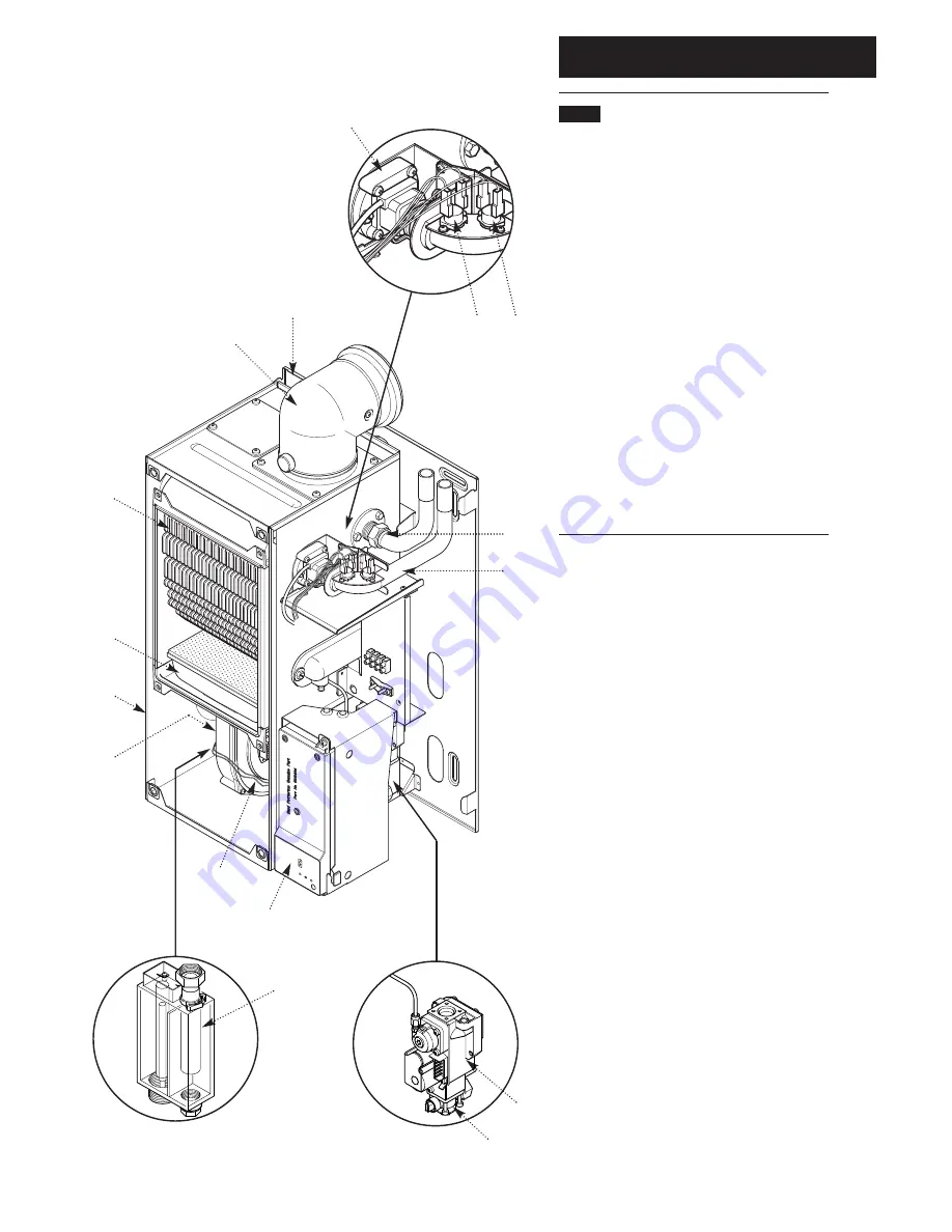
Layout (Figs. 3,4,5 & 6)
1.
Wall Plate
2.
Flue Elbow
3.
Heat Exchanger
4.
Burner
5.
Air Box
6.
Fan Protection Thermostat
7.
Fan Assembly
8.
Condensate Trap
9.
PCB Housing Assembly
10.
Gas Tap
11.
Gas / Air Ratio Valve
12.
Flow Pipe Connection
13.
Return Pipe Connection
14.
Flow Temperature Safety Thermostat - Black
15.
Flow Temperature Thermistor - Red
16.
Flow Switch (dry fire protection)
1
2
3
4
5
6
7
9
8
10
11
15
14
12
13
16
Fig. 4
Fig. 3
Fig. 5
Fig. 6


